
Apparatus for manufacturing a carbonaceous heat source chip

a technology of carbonaceous heat source and apparatus, which is applied in the direction of lighting and heating apparatus, furniture, tobacco, etc., can solve the problem of reducing the installation space of the manufacturing apparatus, and achieve the effect of effective drying

Inactive Publication Date: 2010-01-12
JAPAN TOBACCO INC
View PDF13 Cites 3 Cited by
  • Summary
  • Abstract
  • Description
  • Claims
  • Application Information

AI Technical Summary

Benefits of technology

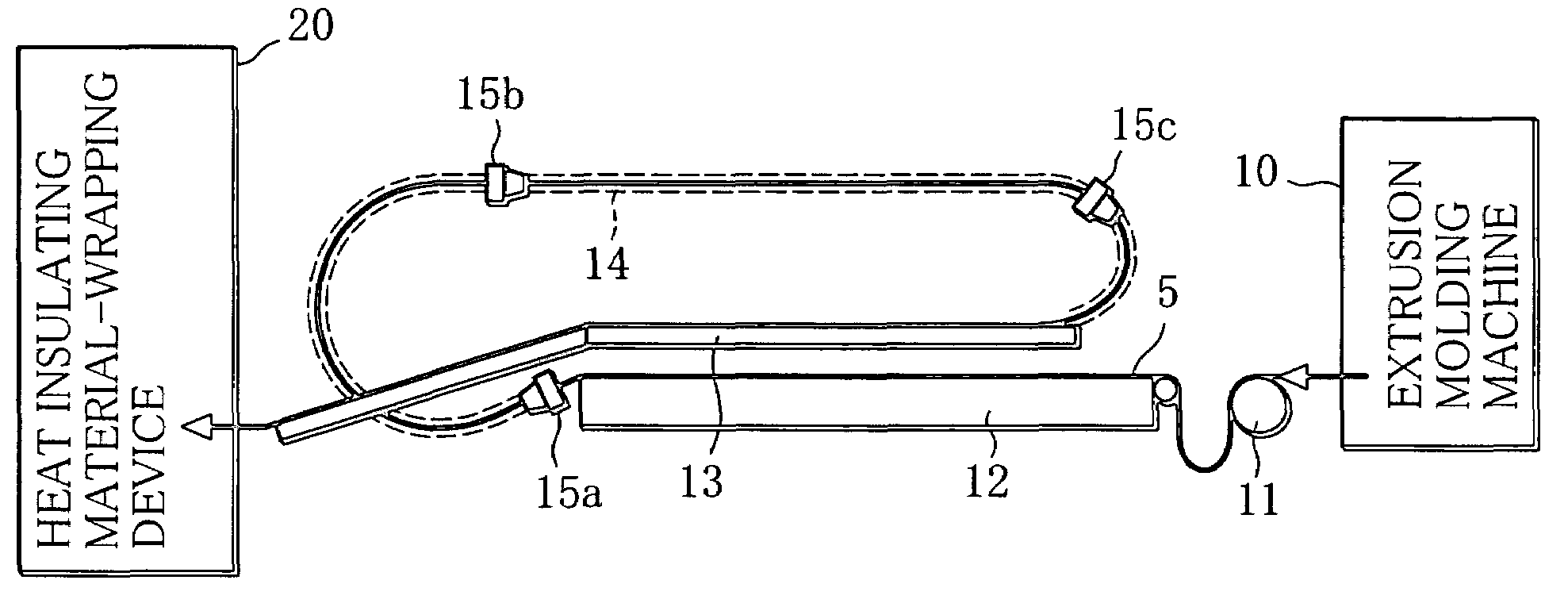
The present invention provides an apparatus for manufacturing a carbonaceous heat source chip by extruding a carbonaceous heat source rod, wrapping it in a heat insulating material, and drying it while maintaining its shape. The apparatus includes an extrusion molding machine, a heat insulating material-wrapping device, and an air amplifier. The extrusion molding machine extrudes the carbonaceous heat source rod with grooves on its surface, and the heat insulating material-wrapping device wraps it in a heat insulating material. The air amplifier creates an airflow that efficiently dries the carbonaceous heat source rod while it is transported through a hollow pipe. The apparatus is designed to ensure that the carbonaceous heat source rod is properly dried without deformation, which ensures the quality of the chip. The extrusion molding machine and the heat insulating material-wrapping device can be positioned close to each other to save installation space. The extrusion molding machine can be designed to have a conveying path for the carbonaceous heat source rod, and the air amplifier can be placed at the inlet and middle of the hollow pipe to create an airflow that smoothly transfers the heat source rod. The heat insulating material-wrapping device can be adjusted to regulate the slack length of the carbonaceous heat source rod. The apparatus can also include a movable carrying path and a cutting device for efficient handling of the carbonaceous heat source rod.

Problems solved by technology

This downsizes the apparatus for manufacturing a carbonaceous heat source chip as a whole and therefore reduces an installation space for the manufacturing apparatus.

Method used


Image

  • Apparatus for manufacturing a carbonaceous heat source chip
  • Apparatus for manufacturing a carbonaceous heat source chip
  • Apparatus for manufacturing a carbonaceous heat source chip

Examples


Embodiment Construction

[0027]An apparatus for manufacturing a carbonaceous heat source chip according to one embodiment of the present invention will be described below with reference to the drawings.

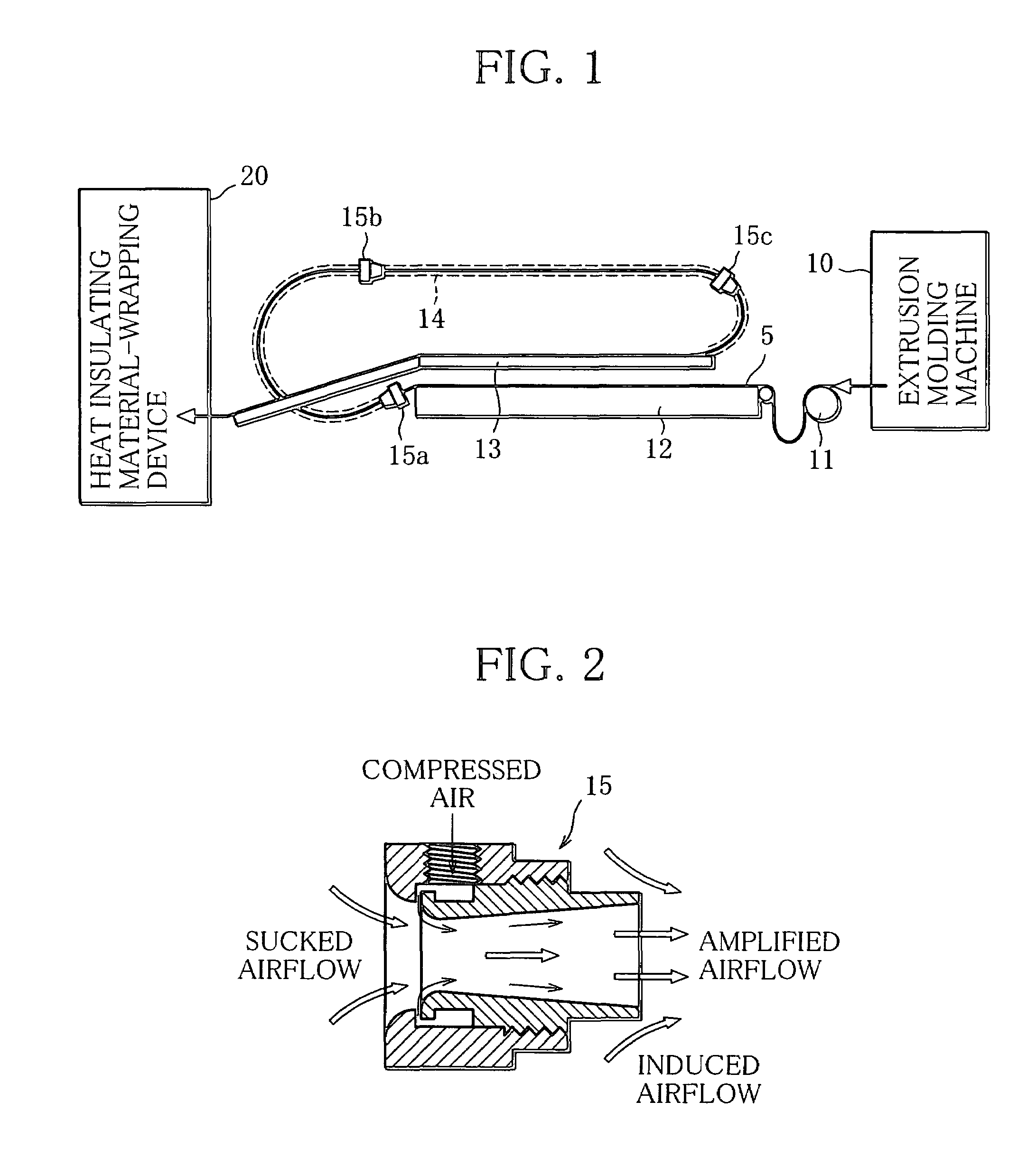
[0028]As illustrated in FIG. 1, the apparatus for manufacturing a carbonaceous heat source chip has an extrusion molding machine 10 that continuously fabricates a carbonaceous heat source rod 5 and a heat insulating material-wrapping device 20 that wraps the carbonaceous heat source rod 5 in a heat insulating material 6 having prescribed thickness, which is made of glass fiber or the like. As the extrusion molding machine 10 and the heat insulating material-wrapping device 20 have been conventionally well known, detail descriptions thereof will be omitted.

[0029]The apparatus for manufacturing a carbonaceous heat source chip is basically constructed so that the moist carbonaceous heat source rod 5 that is continuously extrusion-molded by the extrusion molding machine 10 is sequentially supplied through a conve...


PUM

PropertyMeasurementUnit
diameteraaaaaaaaaa
temperatureaaaaaaaaaa
diameteraaaaaaaaaa

Abstract

Apparatus for manufacturing a carbonaceous heat source chip, capable of drying an extrusion-molded carbonaceous heat source rod to proper hardness and supplying the same to a heat insulating material-wrapping device. The apparatus includes a hollow pipe that forms a conveying path for transporting the carbonaceous heat source rod continuously extrusion-molded by an extrusion molding machine, to the heat insulating material-wrapping device. The apparatus forms an airflow running through the hollow pipe by means of an air amplifier, and transports the carbonaceous heat source rod while drying the rod by using the airflow.

Description

[0001]This application is a Continuation of copending PCT International Application No. PCT / JP2004 / 016407 filed on Nov. 5, 2004, which designated the United States, and on which priority is claimed under 35 U.S.C. §120. This application also claims priority under 35 U.S.C. §119(a) on Patent Application No(s). 2003-384148 filed in Japan on Nov. 13, 2003. The entire contents of each of the above documents is hereby incorporated by reference.TECHNICAL FIELD[0002]The present invention relates to an apparatus for manufacturing a carbonaceous heat source chip installed in a tip end portion of a cigarette or the like together with an aerosol generating material and used for heating the aerosol generating material.BACKGROUND ART[0003]As an alternative to a cigarette and the like, a smoking article formed by wrapping a carbonaceous heat source chip 1, an aerosol generating material 2 such as tobacco leaves, and a mouthpiece (filter) 3 in wrapping paper 4 into a cigarette-like shape as illust...

Claims


Application Information

Patent Timeline
Patent Type & Authority Patents(United States)
IPC IPC(8): A24D1/10B29C47/88F26B3/08F26B7/00A24B15/00A24B15/16B29C48/355
CPCA24B15/165
Inventor HOSOYA, NOBUOOHINATA, HAJIMEBABA, YASUOKOBAYASHI, MASAAKITAKAHASHI, KAZUEI
Owner JAPAN TOBACCO INC
Learn More