Cast ventilation system

Inactive Publication Date: 2000-09-19
BRUDER MICHAEL R
View PDF3 Cites 32 Cited by
  • Summary
  • Abstract
  • Description
  • Claims
  • Application Information

AI Technical Summary

Benefits of technology

In brief, the ventilation system of the present invention comprises a tube insertable through an opening in the cast so that one end of the tube is open to the limb while the other end of the tube is open to the outside surface of the cast. A source of pressurized air is then fluidly connected to th

Problems solved by technology

One common problem associated with a cast placed over a broken limb occurs when the area between the inside surface of the cast and the limb becomes wet.
When thi

Method used


Image

  • Cast ventilation system
  • Cast ventilation system
  • Cast ventilation system

Examples


Embodiment Construction

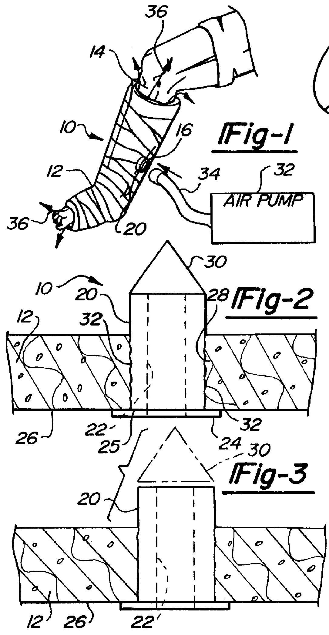
With reference first to FIG. 1, a preferred embodiment of the cast ventilation system 10 of the present invention is there shown for use with a cast 12 positioned around a broken limb 14, such as a leg. In the conventional fashion, the cast 12 is made of a rigid material which prevents movement of the limb 14 while the bone or other injury heals.

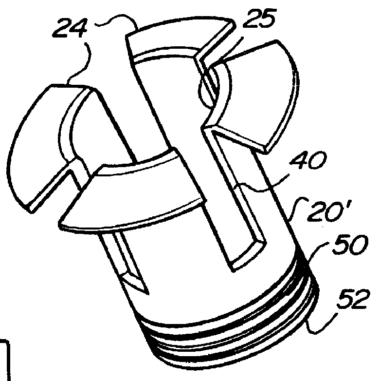
Referring now to FIG. 2, the ventilation system 10 is there shown in greater detail and comprises an elongated tube 20 having an internal bore 22. The tube 20 is preferably cylindrical in shape although other shapes can alternatively be used.

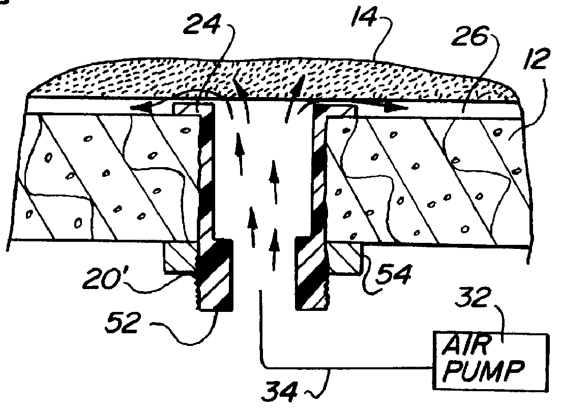
Still referring to FIG. 2, an outwardly extending flange 24 is provided at an inner end 25 of the tube 20 and this flange 24 abuts against an inside surface 26 of the cast 12. The inside surface 26, in turn, faces the patient limb 14 (FIG. 1).

The tube 20 extends entirely through an opening 28 formed through the cast 12 and preferably includes a cone 30 coaxially formed at its outer end. The tube 20 also ...


PUM


Abstract

A ventilation system is disclosed for a cast of the type which encompasses a limb with a rigid material such that an inside surface of the cast faces the limb while an outside surface of the cast is spaced outwardly from the inside surface. The ventilation system includes a tube insertable through the cast so that one end of the tube is open to the limb while the other end of the tube is open to the outside surface of the cast. A source of pressurized air is then fluidly connected to the other or outside end of the tube thus forcing air flow through the tube and into the area between the inside surface of the cast and the limb.

Description

I. Field of the InventionThe present invention relates to a ventilation system for a cast.II. Description of the Prior ArtWhenever a limb, such as a leg or arm, is broken, the limb is typically placed in a cast in order to hold the limb rigid while the broken bone or other injury mends. These previously known casts typically are constructed from a gauze material wrapped around the limb which is then in turn covered with a rigid material, such as plaster. The rigid material, of course, forms the cast to hold the limb against movement such that an inside surface of the cast faces towards the limb while the outside surface is outwardly spaced from the inside surface and faces outwardly.One common problem associated with a cast placed over a broken limb occurs when the area between the inside surface of the cast and the limb becomes wet. When this occurs, an itching sensation of the broken limb results. However, since the cast encompasses the broken limb, the limb cannot be easily or ef...

Claims


Application Information

Patent Timeline
IPC IPC(8): A61F13/04
CPCA61F13/046
Inventor BRUDER, MICHAEL R.
Owner BRUDER MICHAEL R
Why Eureka
Try Eureka