
Method for forming pattern, thin film transistor, display device, method for manufacturing thereof, and television apparatus

a technology of thin film transistors and manufacturing methods, applied in the direction of photomechanical equipment, instruments, originals for photomechanical treatment, etc., can solve the problems of inability to contribute inability to make a contribution to a drastic reduction in the number of steps, and theoretical difficulties, so as to achieve high-reliability display, reduce material loss and cost, and good control

Inactive Publication Date: 2010-01-05
SEMICON ENERGY LAB CO LTD
View PDF34 Cites 49 Cited by
  • Summary
  • Abstract
  • Description
  • Claims
  • Application Information

AI Technical Summary

Benefits of technology

The present invention aims to reduce the number of steps and cost associated with the manufacturing process of a TFT, electronic circuit, and display device. It does this by simplifying the manufacturing process by using a photocatalyst to modify the surface of a substrate, and a method for forming a pattern using a composition containing a pattern forming material. The invention also provides a technique for forming wiring patterns and display patterns with good control over their shapes. Additionally, the invention provides a method for manufacturing a thin film transistor using a photocatalyst and a material containing a fluorocarbon chain. Overall, the invention improves the efficiency and accuracy of the manufacturing process and reduces the cost of the resulting product.

Problems solved by technology

Therefore, as the number of the photolithography steps is increased, the manufacturing cost is inevitably increased.
However, in the technique disclosed in Reference 1, only some of the plural photolithography steps in a TFT manufacturing process are replaced by printing method, and no contribution is made to a drastic reduction in the number of steps.
It is theoretically difficult, from a technical standpoint, to expose a large substrate which is more than one meter on a side to light all at once using the light exposure apparatus.

Method used


Image

  • Method for forming pattern, thin film transistor, display device, method for manufacturing thereof, and television apparatus
  • Method for forming pattern, thin film transistor, display device, method for manufacturing thereof, and television apparatus
  • Method for forming pattern, thin film transistor, display device, method for manufacturing thereof, and television apparatus

Examples


embodiment mode 1

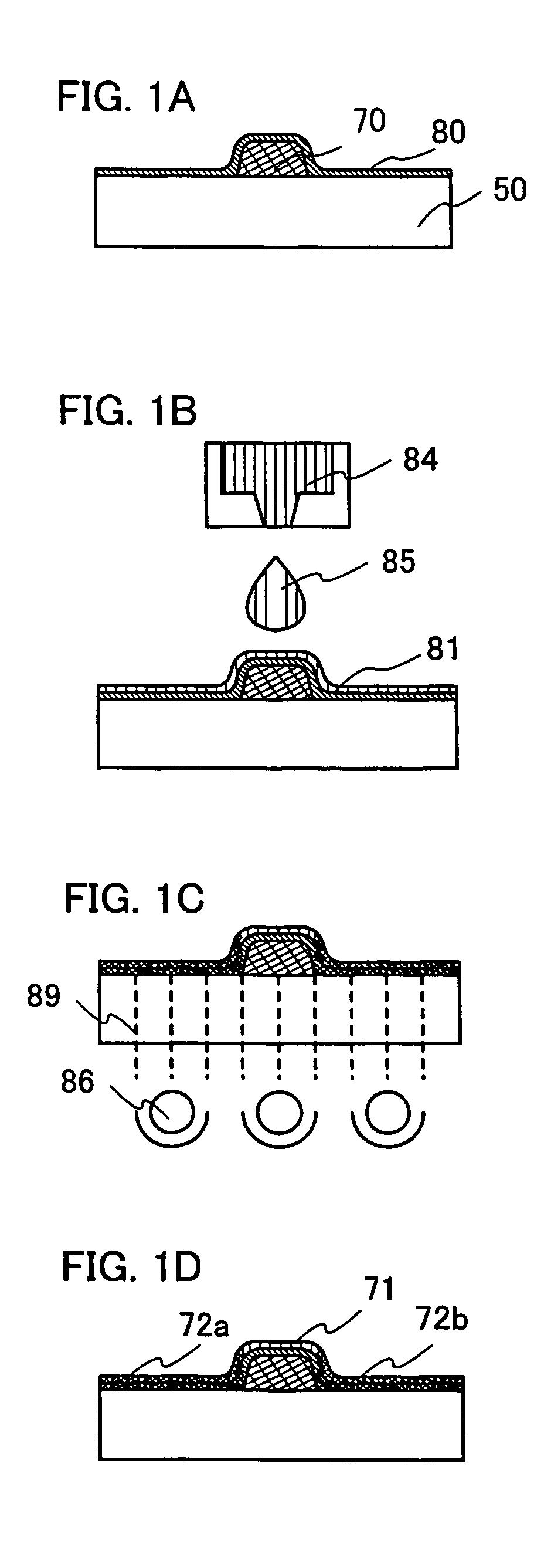
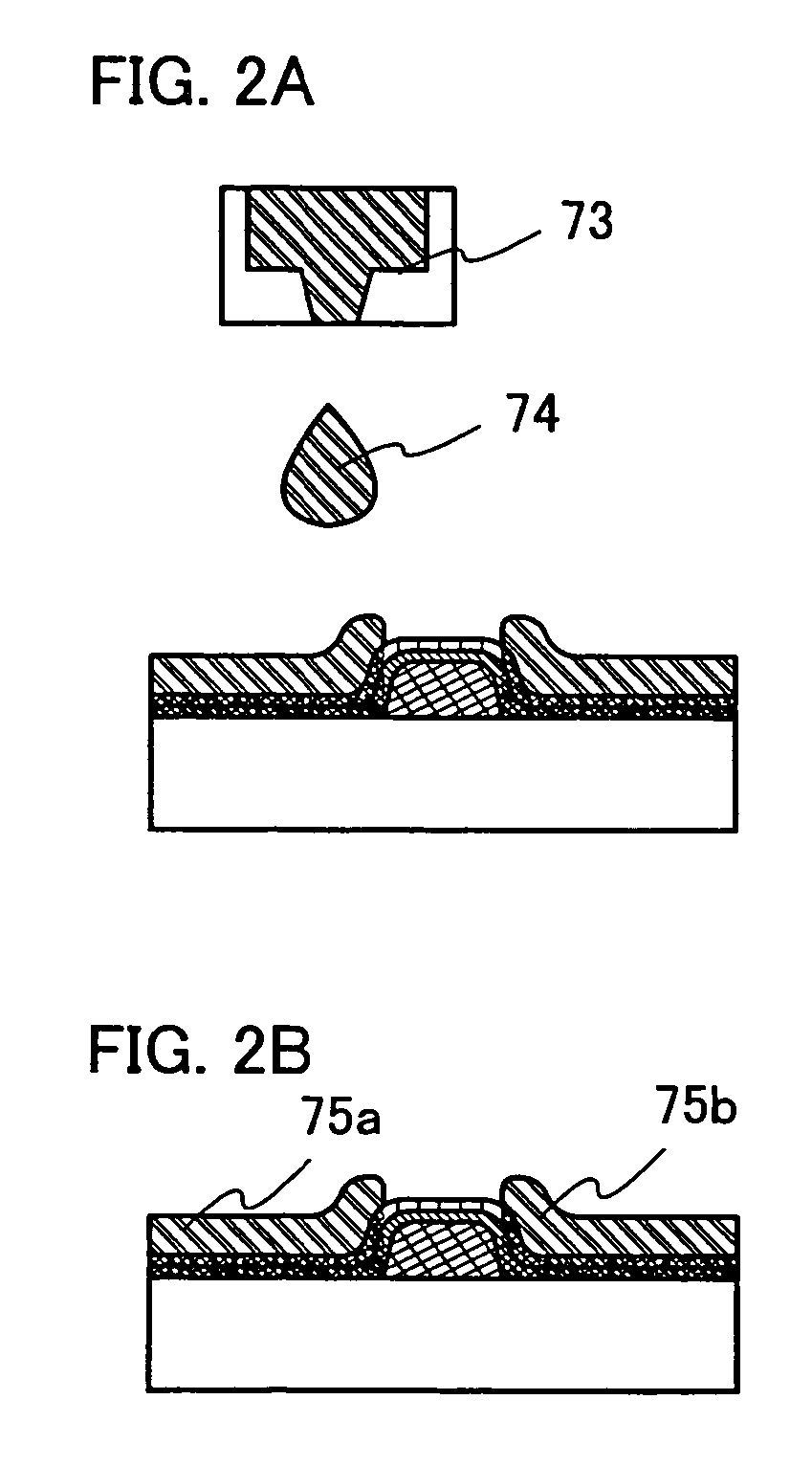
[0055]An embodiment mode according to the present invention is described with reference to FIGS. 1A to 1D, 2A and 2B, and 28.

[0056]One feature of the present invention is that at least one or more of patterns required to manufacture a display panel, such as a wiring layer, a conductive layer for forming an electrode, or a mask layer for forming a predetermined pattern is / are formed by a method capable of selectively forming a pattern to manufacture a display device. In the present invention, a pattern denotes a conductive layer such as a gate electrode layer, a source electrode layer, or a drain electrode layer; a semiconductor layer; a mask layer; an insulating layer; or the like, which constitutes a thin film transistor and a display device, and the pattern includes any component formed so as to have a predetermined shape. A droplet discharge (ejection) method (including an ink-jet method, depending on its mode) that can form a conductive layer, an insulating layer, or the like in...

embodiment mode 2

[0091]An embodiment mode according to the present invention will be described with reference to FIGS. 3A to 3C, 4A to 4C, 5A to 5C, 6A to 6C, 7A to 7C, 8A to 8C, 9A, 9B, 14A to 14C, 15A and 15B. More specifically, a method for manufacturing a display device having a channel etch type thin film transistor according to the present invention will be described. Each of FIGS. 3A, 4A, 5A, 6A, 7A, and 8A shows a top view of a pixel portion in a display device, each of FIGS. 3B, 4B, 5B, 6B, 7B, and 8B shows a cross-sectional view taken along line A-C in FIGS. 3A, 4A, 5A, 6A, 7A, and 8A, and each of FIGS. 3C, 4C, 5C, 6C, 7C, and 8C shows a cross-sectional view taken along line B-D in FIGS. 3A, 4A, 5A, 6A, 7A, and 8A.

[0092]FIG. 14A is a top view showing a structure of a display panel according to the present invention. A pixel portion 2701 in which pixels 2702 are arranged in matrix, a scan line input terminal 2703, and a signal line input terminal 2704 are formed over a substrate 2700 having...

embodiment mode 3

[0167]An embodiment mode of the present invention will be described with reference to FIGS. 10A to 10C and FIGS. 11A and 11B. In this embodiment mode, a display device is manufactured by using a top gate type (an inverted staggered type) thin film transistor as a thin film transistor. An example of a liquid crystal display device using a liquid crystal material as a display element is shown. Accordingly, the same part or a part having similar function will not be repeatedly explained. Note that FIGS. 10A to 10C and FIGS. 11A and 11B show cross-sectional views of the display device.

[0168]Also in this embodiment mode, light irradiation is carried out through a substrate to modify the irradiated area to change the wettability thereof by utilizing the photo activity of a photocatalyst.

[0169]A source / drain electrode layer 330 and a source / drain electrode layer 308 are formed over a light-transmitting substrate 300. The electrode layers are formed by a droplet discharge method in this emb...


PUM

PropertyMeasurementUnit
contact anglesaaaaaaaaaa
wavelengthaaaaaaaaaa

Abstract

To provide a display device which can be manufactured with higher efficiency in the use of material through a simplified manufacturing process, and a method for manufacturing the display device. Another object is to provide a technique by which patterns of a wiring the like which constitutes the display device can be formed to a desired shape with good control. In a method for forming a pattern according to the present invention, a mask is formed over a light-transmitting substrate; a first region including a photocatalyst is formed over the substrate and the mask; the photocatalyst is irradiated with light through the substrate to modify a part of the first region; a second region is formed; and a composition containing a pattern forming material is discharged to the second region, thus, a pattern is formed. The mask does not transmit light.

Description

BACKGROUND OF THE INVENTION[0001]1. Field of the Invention[0002]The present invention relates to a method for forming a pattern, a thin film transistor and a manufacturing method thereof, a display device and a manufacturing method thereof, and a television apparatus using the same.[0003]2. Description of the Related Art[0004]A thin film transistor (hereinafter, referred to as a “TFT”) and an electronic circuit using the thin film transistor are manufactured by stacking various types of thin films of such as a semiconductor, an insulator, a conductor over a substrate and then, appropriately forming a predetermined pattern by photolithography. The photolithography is a technique of transferring a pattern of a circuit or the like formed with a material which does not transmit light over a transparent flat surface, referred to as a photomask, onto an objective substrate by utilizing light. The technique has been widely used in the manufacturing processes of a semiconductor integrated c...

Claims


Application Information

Patent Timeline
Patent Type & Authority Patents(United States)
IPC IPC(8): H01L21/00G03F9/00G03F7/004G03F7/20H01L21/208H01L21/28H01L21/3205H01L21/336H01L21/77H01L29/49H10N10/856
CPCH01L21/28008H01L27/1292H01L29/4908H01L29/66765H01L27/1285H01L21/32051G03F7/0043G03F7/201
Inventor FUJII, GEN
Owner SEMICON ENERGY LAB CO LTD
Learn More