
Printing stock for use in printing composite signs, methods and apparatus for printing such signs, and methods for manufacturing such printing stock

a composite sign and printing technology, applied in the field of printing stock, can solve the problems of time-consuming test, inability to meet the needs of people, cost and turn-around time that are not acceptable to people,

Inactive Publication Date: 2010-01-05
CCL LABEL INC
View PDF103 Cites 37 Cited by
  • Summary
  • Abstract
  • Description
  • Claims
  • Application Information

AI Technical Summary

Benefits of technology

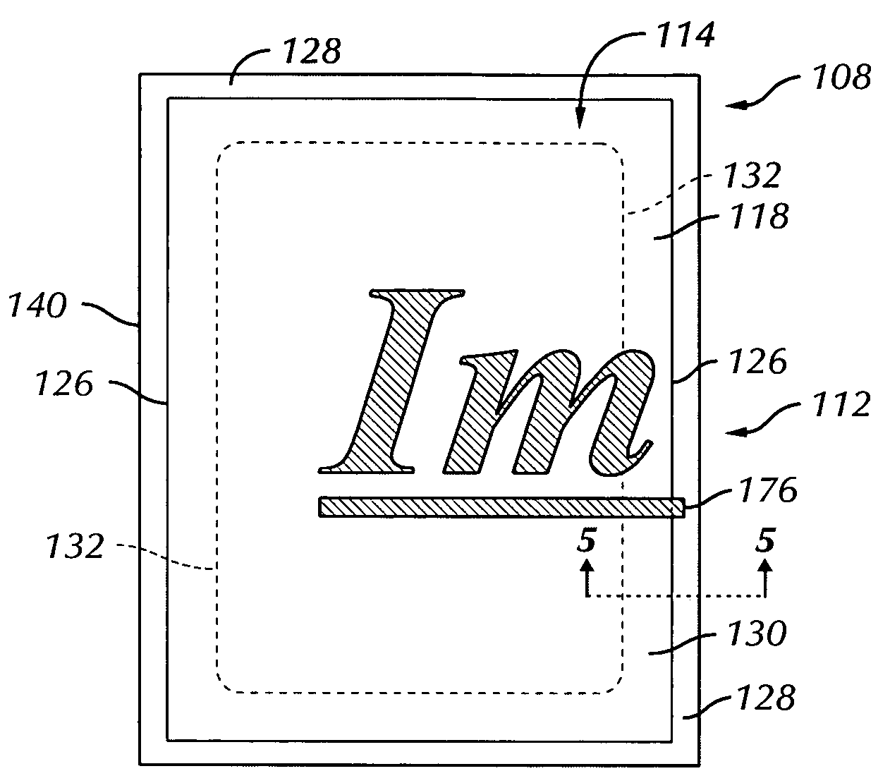
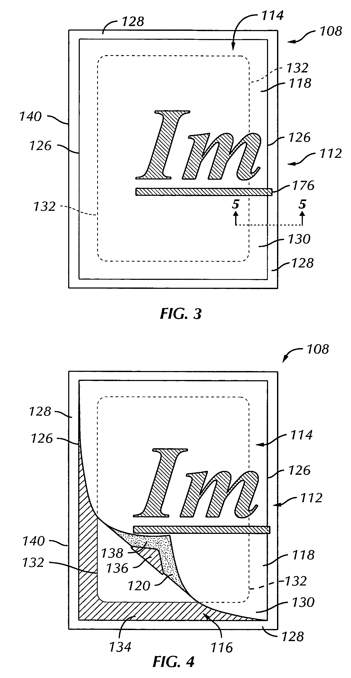
The present invention relates to printing stock and a system for printing and forming larger assemblies suitable for displaying a sign or the like. The invention also relates to methods and apparatus for utilizing such printing stock in making signs. The invention provides a way to efficiently and easily make signs on a small-office, home-office (SOHO) system. The printing stock includes a face sheet and a backing sheet, with the sheets arranged in a pattern to form a desired image of the sign. The face sheet has a printing surface for receiving ink and an adhesive surface for receiving the backing sheet, with the face cut forming a margin and a face sub-sheet. The backing sheet has a backing cut forming a border and a backing sub-sheet. The sheets of printing stock may be configured to form a sign without a dedicated surface or with a carrier. The computer with the software program can process an image into a plurality of sub-images for printing on a corresponding plurality of sheets of printing stock. The printing stock has a face sheet with a margin and a face sub-sheet, and the backing sheet has a border and a backing sub-sheet. The backing cut is formed so that there is a relatively large exposed adhesive portion along one of the sides, with relatively small exposed adhesive portions along the other sides, and sections of the backing cut extend spatially beyond the face cut to be juxtaposed over the margin of the face sheet, thereby forming one or more tab sections of the backing sub-sheet for facilitating the removal of the backing sub-sheet from the face sub-sheet.

Problems solved by technology

However, this may involve a cost and a turn-around time that is not acceptable to a person.
Moreover, the Rudin patent discusses an extensive and time-consuming test-printing process whereby the user manually adjusts the print margins of the image so that the edges of the image precisely align with the die cuts around the central image area of the sheets.
While the above options may have cost advantages over professionally made signs, there are drawbacks.
For example, a considerable amount of manual work needs to be employed to make the sign, particularly in ensuring that sheets are precisely printed and aligned, butting up against each other in a side-to-side arrangement.
If there is any printer misregistration or skewing, then this cannot be compensated for, and the resulting images are likely to be misaligned when assembled.
Moreover, if the printed image or graphic does not extend to the edges, then the user cannot align the sheets with the printed image but rather needs to “eyeball” or guess where to position adjacent sheets that form the sign.
In addition, the manual cutting of the unprinted edges may result in an imperfect sign with breaks or gaps in the text or image of the sign.
Further along these lines, if the sheets are not square for any reason (e.g., slight distortion of the central print area during removal from the sheet, inaccurate die cutting, etc.), then at least one of the abutting edges will not line up perfectly, thereby leaving a visible gap between sheets.
In addition, any shrinkage in the sheets caused by low humidity may cause gaps to form between adjacent sheets.
Finally, old tractor-feed printers could print large rectangular banners; however, the banners were generally of poor quality and limited in height by the standard size of paper utilized by tractor-feed printers.

Method used


Image

  • Printing stock for use in printing composite signs, methods and apparatus for printing such signs, and methods for manufacturing such printing stock
  • Printing stock for use in printing composite signs, methods and apparatus for printing such signs, and methods for manufacturing such printing stock
  • Printing stock for use in printing composite signs, methods and apparatus for printing such signs, and methods for manufacturing such printing stock

Examples


Embodiment Construction

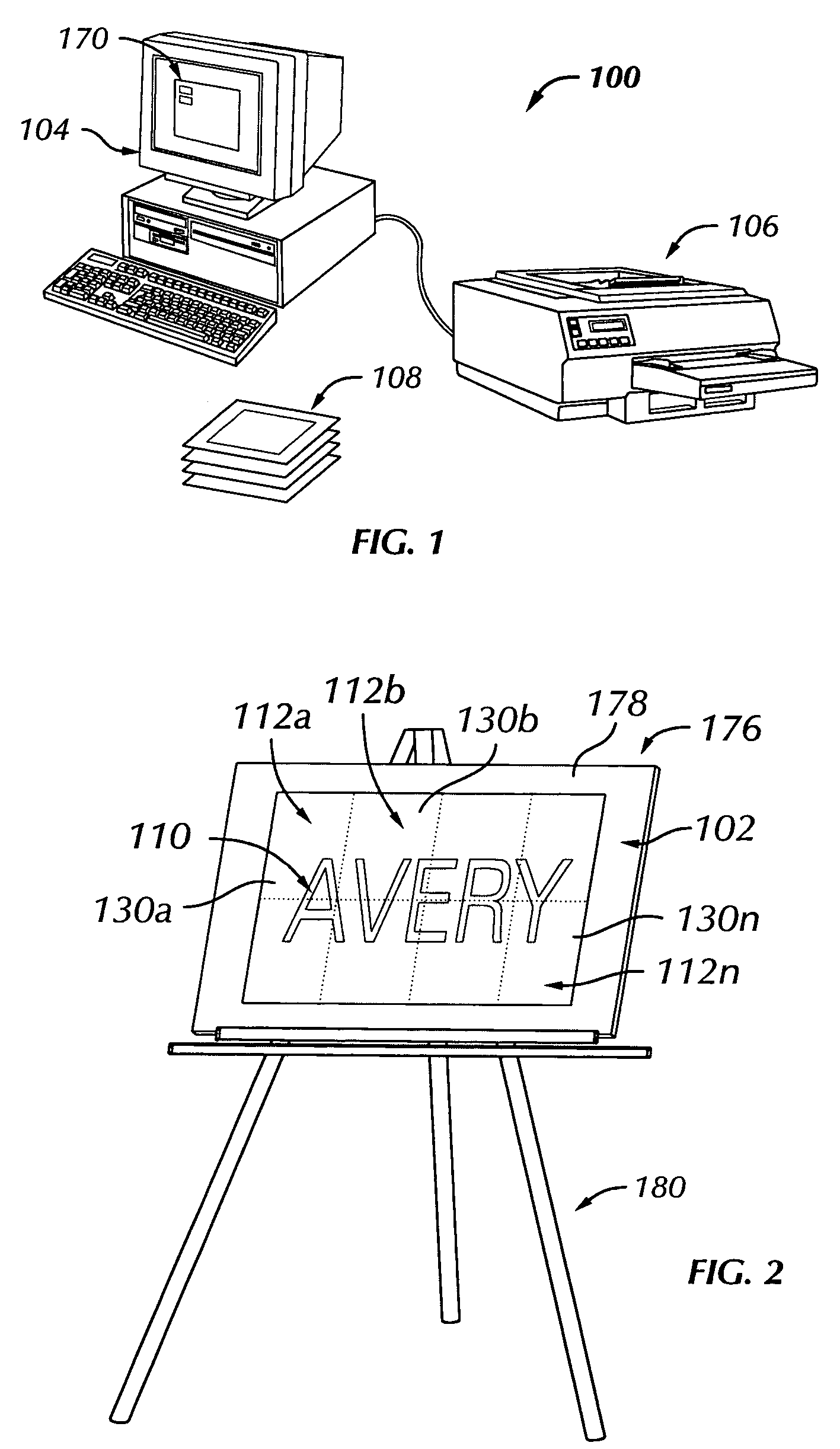
[0069]Referring more particularly to FIGS. 1 and 2 of the drawings, an improved system 100 for printing a sign 102 may include a computer 104, a printer 106, and a plurality of sheets 108 of printing stock. The system 100 may be utilized when it is desired to print a large sign—that is, a sign larger than a single standard-sized sheet of paper (e.g., A4, 8½×11 inches, or legal size)—with a standard small-office, home-office (SOHO) or home printer such as an inkjet printer or a laser printer.

[0070]For the purposes of this description, the sign 102 includes a printed composite image 110 comprised of a plurality of printed sub-images 112a, 112b, . . . , 112n. The composite image 110 is represented by “AVERY” in FIG. 2, with each of the sub-images 112 including a respective portion of “AVERY”, which will be discussed in detail below.

[0071]Referencing FIGS. 3, 4, and 5, each sheet 108 of printing stock may include a face sheet 114 and a backing sheet 116. The face sheet 114 may include a...


PUM

PropertyMeasurementUnit
sizeaaaaaaaaaa
sizesaaaaaaaaaa
sizeaaaaaaaaaa

Abstract

Printing stock for use in making a sign that includes a face sheet and a backing sheet. The sign is formed, for example, by overlapping a plurality of face sub-sheets of the printing stock, with the face sub-sheets arranged in a pattern to form a desired image of the sign. The face sheet includes a printing surface for receiving ink and an adhesive surface for receiving the backing sheet. The face sheet includes a face cut forming a margin and the face sub-sheet such that at least a portion of the margin is separable from the face sub-sheet. The backing sheet may include a backing cut forming a border and a backing sub-sheet such that at least a portion of the border is separable from the backing sub-sheet so that at least a portion of the adhesive surface of the face sheet is exposable.

Description

BACKGROUND OF THE INVENTION[0001]The present invention relates printing stock for use in small-office, home-office (SOHO) or other printers. The present invention also relates to printing stock that includes adhesive, and to printing stock that is used to form signs or posters that, because of size, would not be able to be printed on a single sheet of printing stock.[0002]Signs and posters are commonly utilized for any number of reasons, for example, for announcing a birthday, the arrival of a baby, an outdoor event at a park, a meeting, and so on. In many cases, the sign or poster is of a large size, that is, larger than a piece of paper having a standard size such as A4, 8½×11 inches, or legal size. Accordingly, a person desiring to make a large-scale sign has a couple of options. One option is to have the sign made professionally. However, this may involve a cost and a turn-around time that is not acceptable to a person.[0003]Another option is to make the sign on a SOHO printer c...

Claims


Application Information

Patent Timeline
Patent Type & Authority Patents(United States)
IPC IPC(8): B32B33/00B65D65/28G06T1/00B32B9/00B41JG09F7/12
CPCG09F7/12Y10T428/1476Y10T428/14Y10T428/15Y10T428/1495Y10T428/1486Y10T428/24777Y10T428/149
Inventor HODSDON, JERRY G.WIEN, THOMAS M.BANKS, DONALD E.WILSON, DOUGLAS W.UGOLICK, RONALDHAMEL, MICHAEL R.
Owner CCL LABEL INC
Learn More