
Multi-bed selective catalytic reduction system

a selective catalytic and catalytic technology, applied in the direction of combustible gas purification/modification, separation processes, lighting and heating apparatus, etc., can solve the problems of toxic elements, bad for the environment, and releasing such combustion waste streams without removing these toxic elements, etc., to achieve the effect of reducing the amount of ammonia used

Active Publication Date: 2009-12-29
CALLIDUS TECH
View PDF7 Cites 23 Cited by
  • Summary
  • Abstract
  • Description
  • Claims
  • Application Information

AI Technical Summary

Benefits of technology

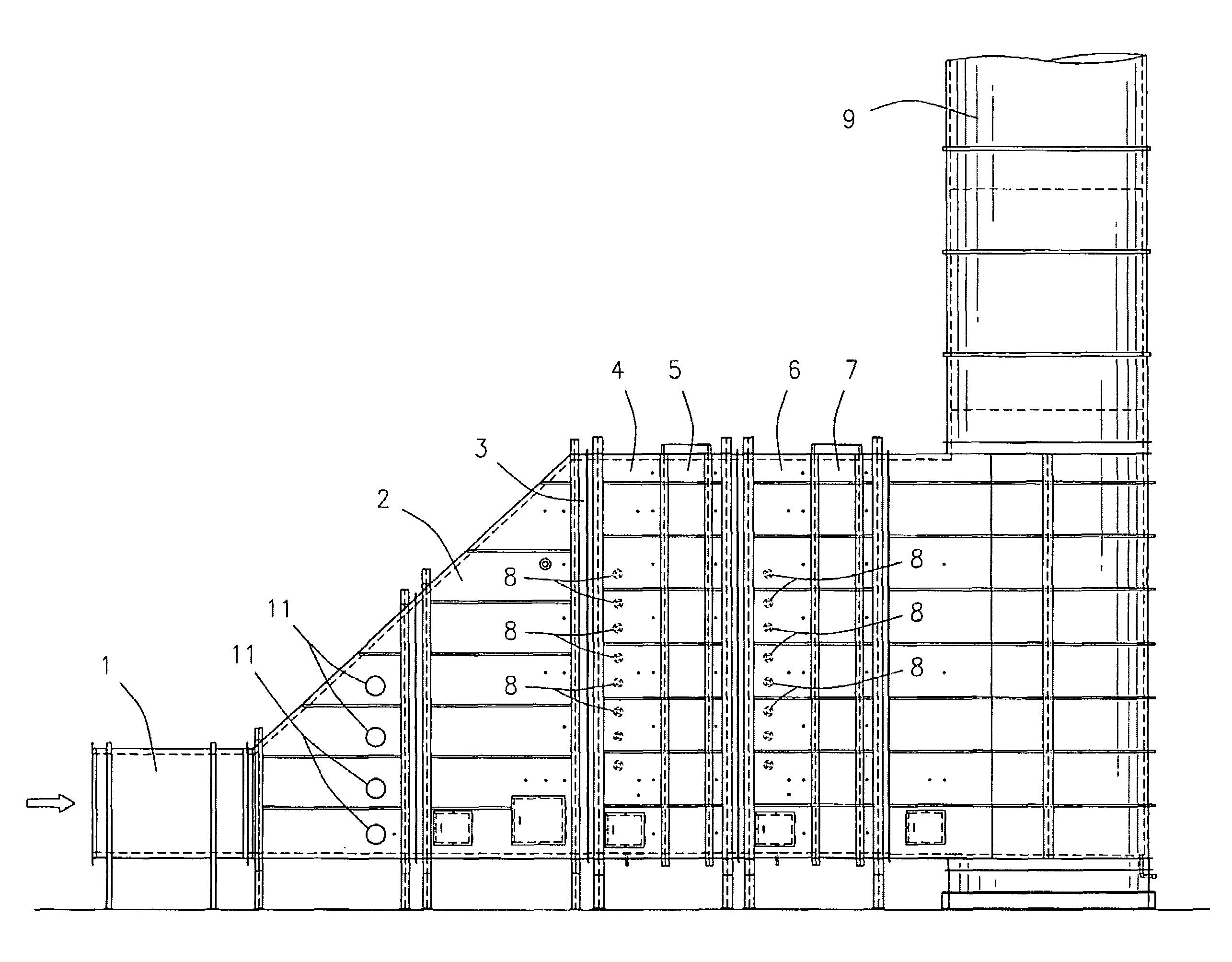
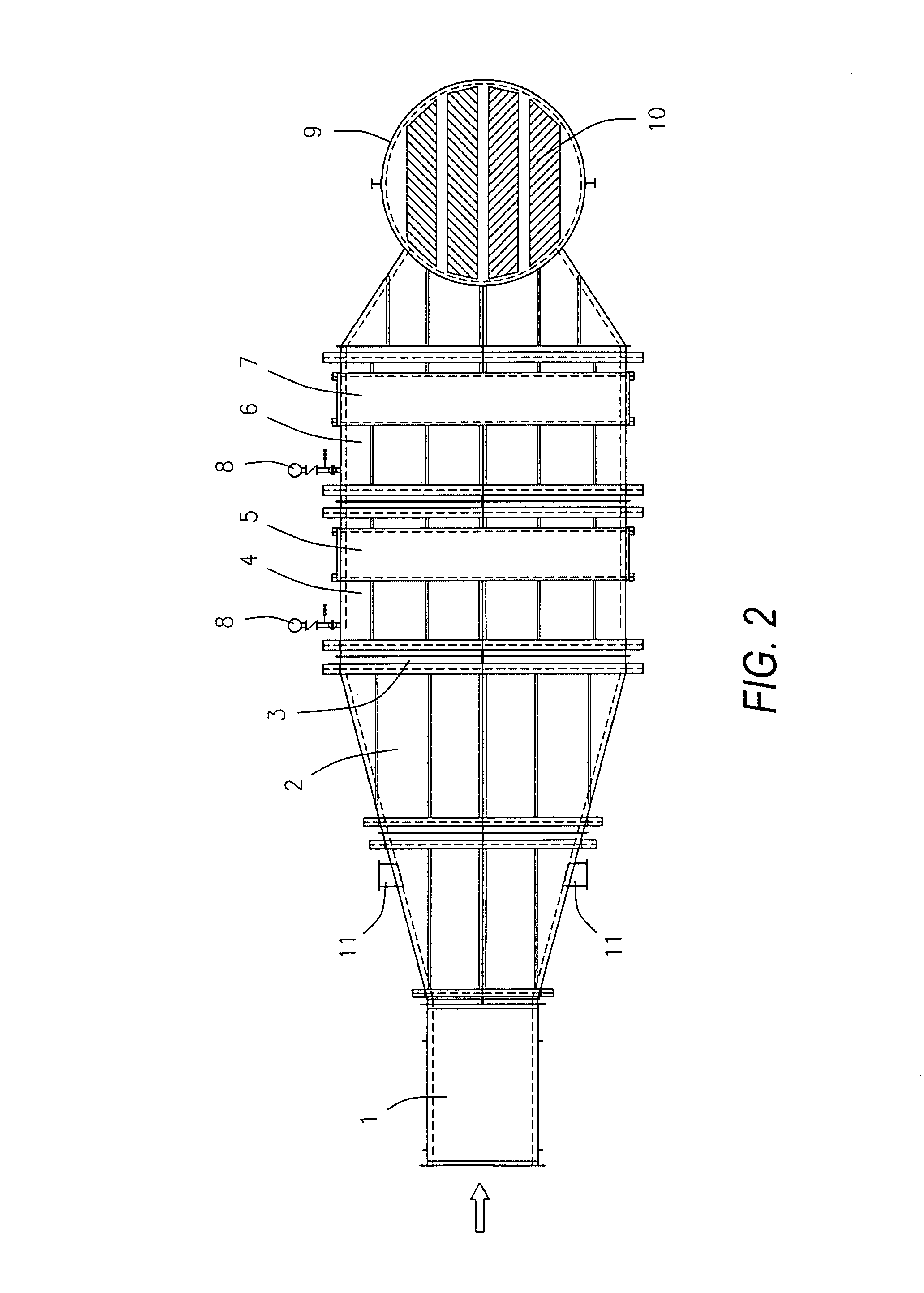
[0007]The multi-bed selective catalytic reduction system may further comprise a distribution grid located between the gas input duct and the plurality of ammonia injection grid assemblies and plurality of selective catalytic reduction catalyst assemblies. Likewise, the multi-bed selective catalytic reduction system may further comprise a silencer in the exhaust stack.
[0008]The multi-bed selective catalytic reduction system may further comprise a plurality of air intake ducts located upstream from the plurality of ammonia injection grid assemblies and plurality of selective catalytic reduction catalyst assemblies and the distribution grid, if it is present. There may be a plurality of fans in fluid communication with the plurality of air intake ducts, and there may be a plurality of dampers located adjacent the plurality of air intake ducts.
[0009]The multi-bed selective catalytic reduction system may further comprise a carbon monoxide catalyst assembly located downstream from the gas input duct.
[0010]The multi-bed selective catalytic reduction system may be used in a method of removing toxic elements from a combustion waste stream, comprising allowing a combustion waste stream comprising one or more toxic elements to enter a multi-bed selective catalytic reduction system; removing toxic elements from said combustion waste stream by passing said combustion waste stream through a first ammonia injection grid assembly and then a first selective catalytic reduction catalyst assembly located within said multi-bed selective catalytic reduction system; removing more toxic elements from said combustion waste stream by passing said combustion waste stream through a second ammonia injection grid assembly and then a second selective catalytic reduction catalyst assembly located within said multi-bed selective catalytic reduction system; and allowing said combustion waste stream to exit said multi-bed selective catalytic reduction system through an exhaust stack.
[0011]This method may further comprise axially distributing the combustion waste stream by passing the combustion waste stream through a distribution grid before passing the combustion waste stream through the first ammonia injection grid assembly. It may likewise further comprise adding tempering air to the combustion waste stream prior to passing the combustion waste stream through the first ammonia injection grid assembly and prior to axially distributing the combustion waste stream, if the distribution grid is present, by allowing tempering air to enter the multi-bed selective catalytic reduction system through a plurality of air intake ducts located upstream of the first ammonia injection grid assembly and the distribution grid, if it is present. Furthermore, the method may comprise forcibly adding tempering air to the combustion waste stream through the use of a plurality of fans in fluid communication with the plurality of air intake ducts. Likewise, the method may furthermore comprise controlling the amount of tempering air added to the combustion waste steam through the use of dampers located adjacent the air intake ducts.
[0012]The method may further comprise removing carbon monoxide from the combustion waste stream by passing the combustion waste stream through a carbon monoxide catalyst assembly located within the multi-bed selective catalytic reduction system.

Problems solved by technology

Waste streams produced from combustion, such as that produced by burning gas, coal, oil, or other carbon-based fuel sources in combustion turbine engines or for other similar uses, typically contain toxic elements, including carbon monoxide (CO) and nitrogen oxide (NOx).
Releasing such combustion waste streams without removing these toxic elements is bad for the environment.
The foregoing art, however, cannot remove a high percentage of NOx from combustion waste streams without requiring the use of extra ammonia, part of which will not be used and will slip past the selective catalytic reduction catalyst and into the environment.
This is particularly a problem as environmental standards continue to rise, such as in California.
With the current systems, high NOx conversion and low ammonia slip are not practical, as the distribution of ammonia required to achieve this performance in a single stage is not achievable with the allowable pressure drop for most systems.
Therefore, for high NOx conversion, more ammonia must be used and more ammonia will be lost, passing through the selective catalytic reduction catalyst without reacting, and thus exiting into the environment as part of the supposedly treated waste stream.

Method used


Image

  • Multi-bed selective catalytic reduction system
  • Multi-bed selective catalytic reduction system
  • Multi-bed selective catalytic reduction system

Examples


Embodiment Construction

[0017]The devices and methods discussed herein are merely illustrative of specific manners in which to make and use this invention and are not to be interpreted as limiting in scope.

[0018]While the devices and methods have been described with a certain degree of particularity, it is to be noted that many modifications may be made in the details of the construction and the arrangement of the devices and components without departing from the spirit and scope of this disclosure. It is understood that the devices and methods are not limited to the embodiments set forth herein for purposes of exemplification.

[0019]The multi-bed selective catalytic reduction system provides a much-improved method for nitrogen oxide (NOx) reduction from a combustion waste stream. This method utilizes a carbon monoxide (CO) catalyst and multiple ammonia injection grids (AIGs) and selective catalytic reduction (SCR) catalysts in a two-stage system for the reduction of toxic elements present in combustion was...


PUM

PropertyMeasurementUnit
pressure dropaaaaaaaaaa
temperatureaaaaaaaaaa

Abstract

A multi-bed selective catalytic reduction system comprising a gas input duct, a first ammonia injection grid assembly located downstream from the gas input duct, a first selective catalytic reduction catalyst assembly located downstream from the first ammonia injection grid assembly, a second ammonia injection grid assembly located downstream from the first selective catalytic reduction catalyst assembly, a second selective catalytic reduction catalyst assembly located downstream from the second ammonia injection grid assembly, and an exhaust stack located downstream from the second selective catalytic reduction catalyst assembly. By passing a combustion waste stream through two sets of ammonia injection grid assemblies and selective catalytic reduction catalyst assemblies, the multi-bed selective catalytic reduction system removes more nitrogen oxide emissions from the waste stream, uses less ammonia to do so, and results in less ammonia emissions than systems with only one ammonia injection grid assembly and selective catalytic reduction catalyst assembly.

Description

FIELD OF THE INVENTION[0001]This invention relates generally to removal of toxic elements from combustion waste streams, and more particularly to removal of nitrogen oxide from combustion waste streams using two sets of ammonia injection grids and selective catalytic reduction catalysts.DESCRIPTION OF THE RELATED ART[0002]Waste streams produced from combustion, such as that produced by burning gas, coal, oil, or other carbon-based fuel sources in combustion turbine engines or for other similar uses, typically contain toxic elements, including carbon monoxide (CO) and nitrogen oxide (NOx). Releasing such combustion waste streams without removing these toxic elements is bad for the environment. Additionally, many places have regulations or laws prohibiting such release. The extent to which CO and NOx may be released into the environment varies widely under these various laws. California, in particular, has a very high standard regarding such emissions. Therefore, producers of such com...

Claims


Application Information

Patent Timeline
Patent Type & Authority Patents(United States)
IPC IPC(8): B01D53/56B01D53/62B01D53/86B01D53/90
CPCB01D53/8631B01D53/8656B01D2257/502B01D2257/404B01D2251/2062
Inventor WIRT, JEFFREY PHILIPOTT, DAN W.DUCK, BRIAN JAMES
Owner CALLIDUS TECH
Learn More