
Method and apparatus for optical level sensing of agitated fluid surfaces

a technology of optical level sensing and fluid surface, which is applied in the direction of liquid/fluent solid measurement, instruments, machines/engines, etc., can solve the problems of lidar tank gauges that operate with such reflectors that cannot be qualified as non-contact instruments, reflectors can no longer be used as liquid contaminants, etc., to achieve accurate and reliable measurements

Active Publication Date: 2009-12-22
LEDDARTECH INC
View PDF19 Cites 36 Cited by
  • Summary
  • Abstract
  • Description
  • Claims
  • Application Information

AI Technical Summary

Benefits of technology

[0013]It is therefore a first object of the present invention to provide a lidar apparatus based on a pulsed time-of-flight modulation scheme in combination with digitization of the captured signal waveforms, and which can perform accurate and reliable measurements of the level of agitated fluids stored in containers or tanks, without any contact with the fluids.
[0014]Another object of the present invention is to provide a method that enables successful retrieval of the signal echo returned from an agitated fluid surface, the method being intended for implementation in the processing unit of a lidar apparatus adapted for level sensing applications wherein the distance to a fluid surface is determined from the position of the signal echo in the recorded signal waveforms.
[0015]It is another object of the present invention to provide a method that enables successful retrieval of the signal echo returned from an agitated fluid surface located below an atmosphere filled with a medium that could cause a significant attenuation of optical beams, the method being intended for implementation in the processing unit of a lidar apparatus dedicated to level sensing applications.

Problems solved by technology

Otherwise, the operation of both types of tank-gauging devices is often plagued by false return echoes due to spurious reflections of the wave energy on the walls of the tank or on the obstacles that could be present in it.
Although a reflector increases substantially the optical feedback from the surface to be gauged, a lidar tank gauge that operates with such a reflector can no longer be qualified as a non-contact instrument.
Hence, the reflector can contaminate the liquid stored in the tank, or the liquid itself can corrode the reflector.
Above all, the need to enclose the floating reflector in a vertical pipe in order to prevent the reflector from moving outside of the surface area illuminated by the light beam is a serious drawback.
The instrument then becomes very intrusive.
Unfortunately, the presence of waves or turbulent conditions at the surface of a liquid also means that the local inclination or tilt angle of the limited surface area that is illuminated by the probe optical beam no longer remains in fixed relationship with the vertical propagation axis of the optical beam.
The collected return signal can then exhibit sizeable amplitude fluctuations, which will often adversely affect the tracking of the useful signal echo coming from the reflection off the liquid surface.
Note that this problem persists when using a solid plane reflector that floats on a liquid surface.
Unfortunately, the use of an optical diffuser does not fully eliminate the amplitude fluctuations of the returned signal, particularly when the wavelength of the waves at the surface of the liquid compares to the diameter of the optical spot size.
In addition, the optical losses undergone during passage through the diffuser and the need for enlarging the field of view of the optical receiver can degrade the signal-to-noise ratio of the recorded signals.
The challenge of remotely measuring the level of disturbed liquid surfaces arises when using microwave tank-gauging radars as well.
The methods rely on spectral averaging and / or spectral filtering of the frequency domain signals, and they are not intended for implementation in tank-gauging devices that operate according to the pulsed TOF principle.
The level sensing of an agitated liquid surface becomes even more difficult when the liquid is also temporarily out of thermodynamical equilibrium with its environment.
Depending on the nature of the liquid and of its temperature, these non-equilibrium conditions can lead to the formation of fog in the atmosphere above the liquid surface.
Likewise, the loading of a tank with a high-pressure filling stream generally causes the formation of clouds of droplets in the atmosphere above the liquid surface.
The difficulty to perform level measurements in both types of conditions, which can occur simultaneously, originates from the fact that fog and droplet clouds can absorb and / or scatter a sizeable fraction of the optical beam energy during the beam propagation from the tank-gauging device to the liquid surface and then back to the device.
The situation compares with the degraded visibility conditions caused by the presence of fog in the air.

Method used


Image

  • Method and apparatus for optical level sensing of agitated fluid surfaces
  • Method and apparatus for optical level sensing of agitated fluid surfaces
  • Method and apparatus for optical level sensing of agitated fluid surfaces

Examples


Embodiment Construction

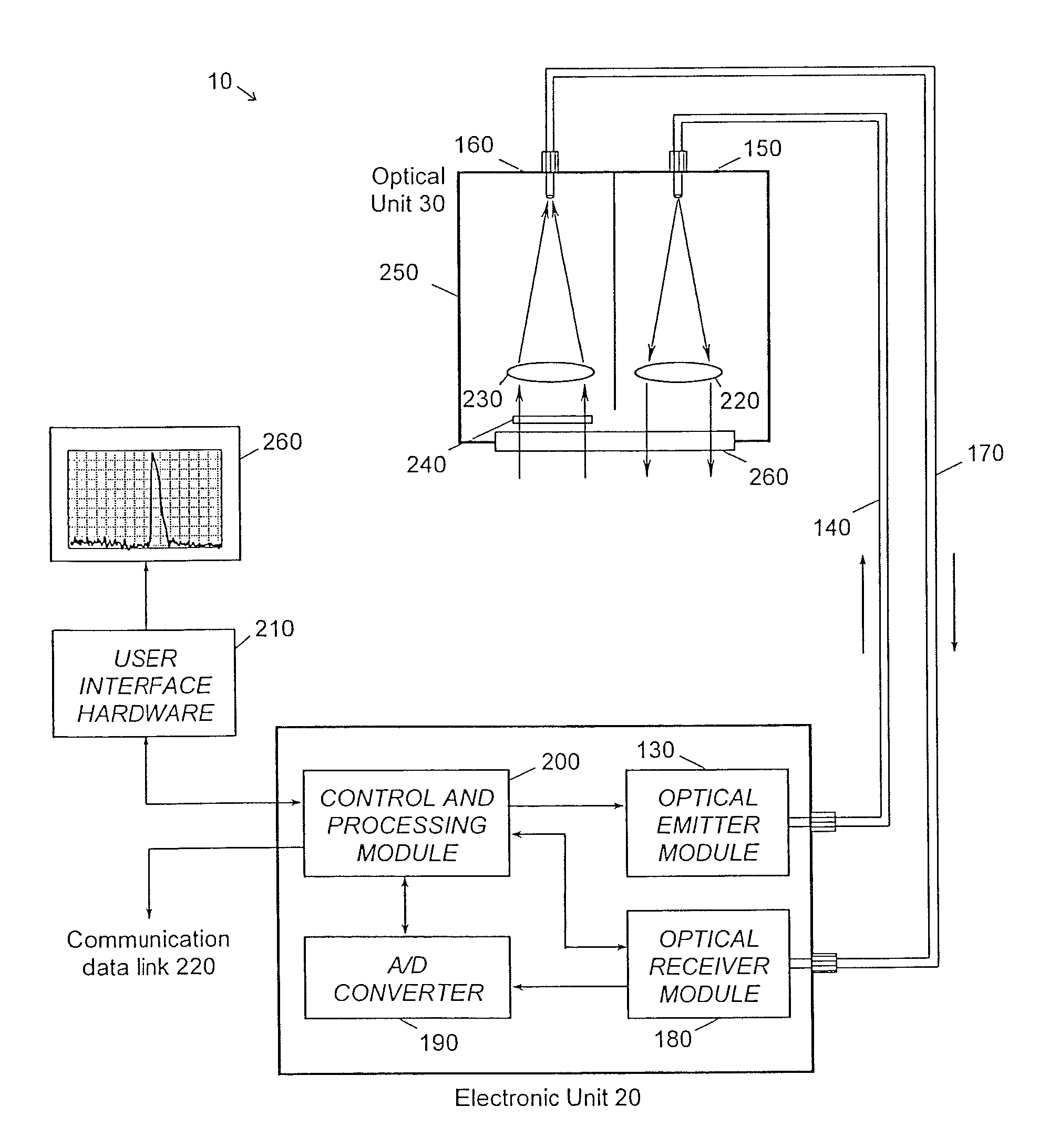
[0028]FIG. 1 is a schematic illustration of a liquid-level measurement application that represents a preferred mode of practicing the invention with its various embodiments. A lidar tank-gauging device 10 is shown in FIG. 1 with a preferred design configuration wherein the device is made up of an electronic unit 20 remote from an optical unit 30, the units being linked to each other only through light transmission means 40. The light transmission means 40 consist preferably of two optical fibers. The optical unit 30 is mounted on the roof of a liquid storage tank or vessel 50, and a window 60 made of a suitable optical material provides optical access to the interior of the tank 50. Although the storage tank shown in FIG. 1 is stationary, the apparatus of the present invention can be used with tanks or containers mounted in transportation means as well. Likewise, both electronic unit 20 and optical unit 30 can be enclosed in the same housing located on the roof of the tank 50 withou...


PUM


Abstract

A method and apparatus provide for non-contact optical measurement of the level of a fluid stored in a tank or container, the surface of the fluid being possibly agitated. The method processes numerically the digitized signal waveforms generated by a lidar apparatus based on a pulsed time-of-flight modulation scheme. A key step of the numerical processing is the computation of a waveform in which each data point is obtained from a statistical estimator of the variability of the amplitude signal echo measured at the distance from the lidar apparatus that corresponds to the rank of the data point in the waveform. The statistical estimator is preferably the standard deviation. By using a statistical estimator of the variability of the captured signal amplitude, the specific signal echo returned from an agitated fluid surface can be greatly amplified as compared to the signal echoes returned from any obstacle or medium that could be present along the path of the optical beam radiated by the lidar apparatus. The method then allows for an efficient retrieval of the useful signal echo from which the level of the fluid surface can be reliably measured with greater accuracy, particularly in situations where the useful signal echo would be buried in a strong signal echo returned from any optically scattering or absorbing medium that would fill in the volume of the tank above the fluid surface.

Description

FIELD OF THE INVENTION[0001]This invention generally relates to a method and apparatus for fluid-level measurement, and more particularly for the optical measurement of the surface level of an agitated fluid under degraded visibility conditions.BACKGROUND OF THE INVENTION[0002]Various types of instruments have been developed for applications related to the monitoring of tank contents, wherein the level of stored materials in either liquid, solid, or slurry state must be measured, either continuously or by discrete height steps. The expressions level measurement and tank gauging refer to the measurement of the height of the top surface of a material stored in a tank or the measurement of the vertical distance that separates the surface of the material from a reference level and are used herein interchangeably. Traditional levelmeter devices include dipsticks, either in manual or electronic form, mechanical float levelmeters, capacitive RF levelmeters, and photoelectric levelmeters. M...

Claims


Application Information

Patent Timeline
IPC IPC(8): G01N15/06G01F23/00
CPCG01F23/2928G01F23/292
Inventor BABIN, FRANCOIS
Owner LEDDARTECH INC
Learn More