
Dielectrophoresis-based particle sensor using nanoelectrode arrays

a nanoelectrode array and particle sensor technology, applied in the direction of liquid/fluent solid measurement, fluid pressure measurement, peptides, etc., can solve the problems of high cost, slow operation speed, and need for skilled personnel, and achieve the effect of facilitating on-chip sample preparation

Inactive Publication Date: 2009-12-22
NASA
View PDF1 Cites 18 Cited by
  • Summary
  • Abstract
  • Description
  • Claims
  • Application Information

AI Technical Summary

Benefits of technology

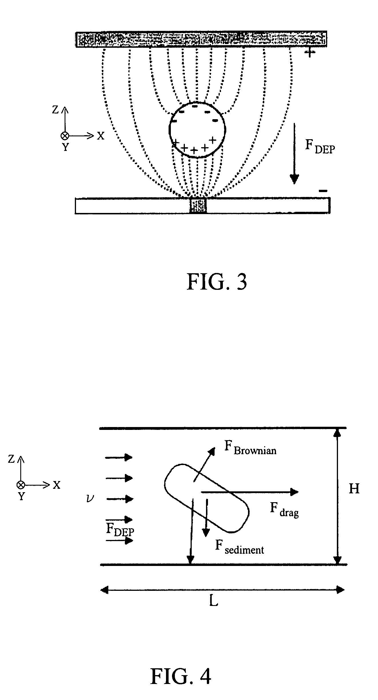
[0007]One key advantage is that an array of NS electrodes can provide an electric field intensity gradient, particularly ∂(E2) / ∂z, that is one or more orders of magnitude greater than the corresponding gradient provided by a conventional microelectrode arrangement.

Problems solved by technology

The main disadvantages are cross-contamination, slow operational speed, high cost and the need for skilled personnel.
This is because of the necessity of processing large sample volumes that is difficult in existing chip platforms.

Method used


Image

  • Dielectrophoresis-based particle sensor using nanoelectrode arrays
  • Dielectrophoresis-based particle sensor using nanoelectrode arrays
  • Dielectrophoresis-based particle sensor using nanoelectrode arrays

Examples


Embodiment Construction

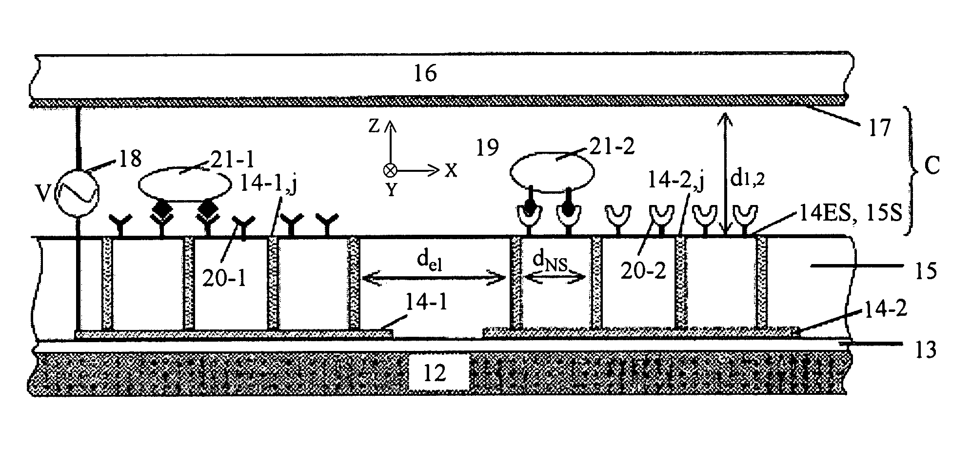
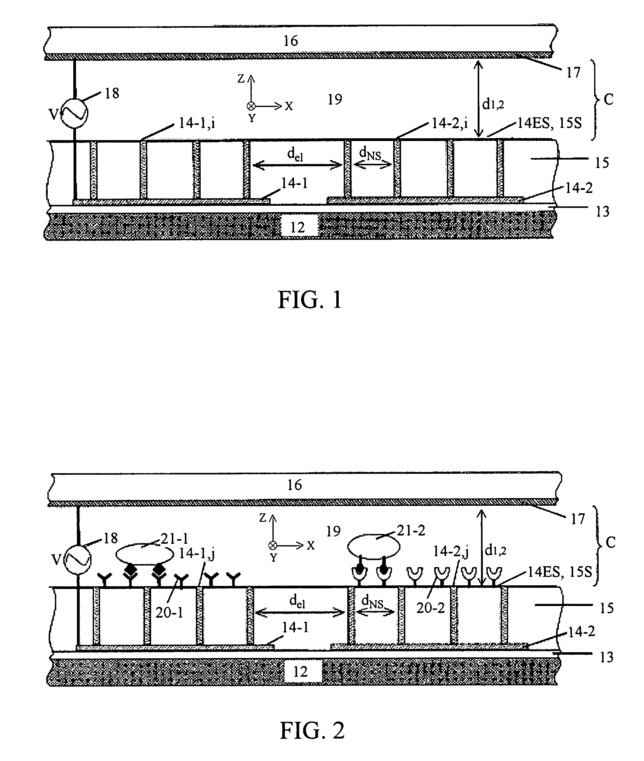
[0016]FIG. 1 schematically illustrates an embodiment 1 of the invention, which includes a substrate 12, a thin insulating first layer 13 (e.g., SiO2, Si3N4, or other) contiguous to a surface of the substrate 12, and an array of spaced apart (first) electrodes 14-i (i=1, . . . , I; I≧1), with each electrode 14-i having an a sub-array of at least first and second spaced apart nanostructure (“NS”) electrodes 14-(i,j) (j=1, . . . , J; J≧2). Optionally, interstitial regions between adjacent NSs 14-(i,j) on the same electrode and / or between adjacent electrodes 14-i are partly or wholly filled with an insulating material 15 (e.g., SiO2, Si3N4, epoxy or other), and the insulating material 15 is planarized by mechanical polishing, chemical etching, chemical mechanical polishing, or plasma etching so that tips of the NSs are exposed, collectively forming an exposed surface 14ES of the electrodes 14-i. The NSs 14-(i,j) may be multi-wall carbon nanotubes (“MWCNTs”) or carbon nanofibers (“CNFs”)...


PUM

PropertyMeasurementUnit
Thicknessaaaaaaaaaa
Distanceaaaaaaaaaa
Angular frequencyaaaaaaaaaa

Abstract

A method for concentrating or partly separating particles of a selected species from a liquid or fluid containing these particles and flowing in a channel, and for determining if the selected species particle is present in the liquid or fluid. A time varying electrical field E, having a root-mean-square intensity E2rms with a non-zero gradient in a direction transverse to the liquid or fluid flow direction, is produced by a nanostructure electrode array, with a very high magnitude gradient near exposed electrode tips. A dielectrophoresis force causes the selected particles to accumulate near the electrode tips, if the medium and selected particles have substantially different dielectric constants. An insulating material surrounds most of each of the nanostructure electrodes, and a region of the insulating material surface is functionalized to promote attachment of the selected species particles to the surface. An electrical property value Z(meas) is measured at the functionalized surface and is compared with a reference value Z(ref) to determine if the selected species particles are attached to the functionalized surface.

Description

FIELD OF THE INVENTION[0001]This invention relates to use of nanostructure electrode arrays and non-constant electrical fields to sense presence of a selected species particle.BACKGROUND OF THE INVENTION[0002]Sample preparation is one of the key functions in detection of biologically important organisms. It involves controlled separation, concentration, and / or manipulation of desired particles from a matrix of interferents. Traditionally, it is performed through separate, standalone centrifugation, magnetic manipulation and filtration systems and then transferred to a detector. The main disadvantages are cross-contamination, slow operational speed, high cost and the need for skilled personnel. Recent efforts are towards the development of lab-on-a-chip systems (“LOC”) with on-chip sample preparation and detection capabilities. Although LOC offers advantages of reduced reagent consumption and reduced waste generation, multiplexing, portability and scalability, the integration of on-c...

Claims


Application Information

Patent Timeline
IPC IPC(8): B03C5/02
CPCB03C5/026B03C5/005
Inventor LI, JUNCASSELL, ALAN M.ARUMUGAM, PRABHU U.
Owner NASA
Learn More