Variable matching circuit
a matching circuit and circuit technology, applied in the field of matching circuits, can solve the problems of difficult radio device to adapt to a wide range of frequency bandwidths, inability to fully exert the performance of the radio device, and high cos
- Summary
- Abstract
- Description
- Claims
- Application Information
AI Technical Summary
Benefits of technology
Problems solved by technology
Method used
Image
Examples
embodiment 1
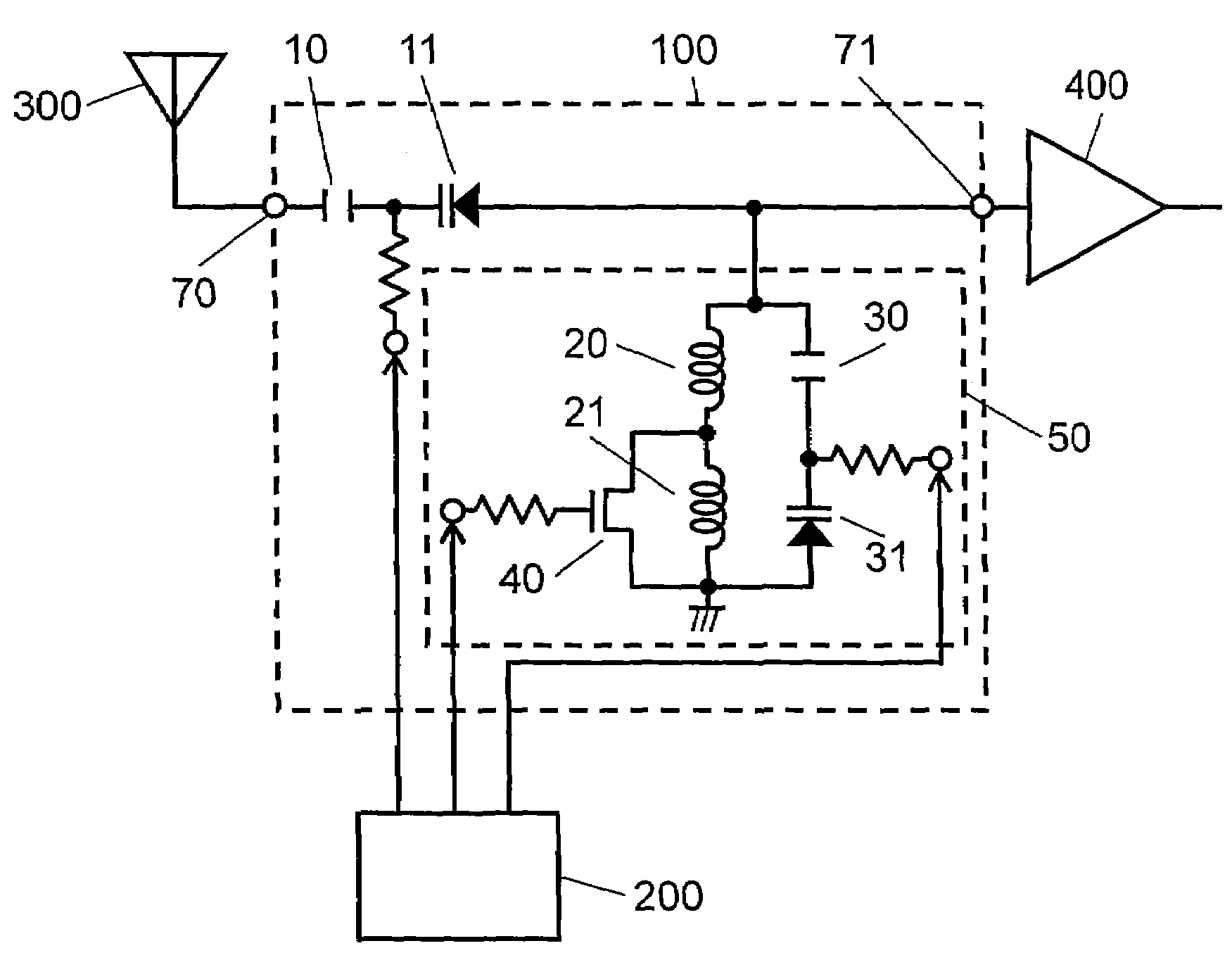
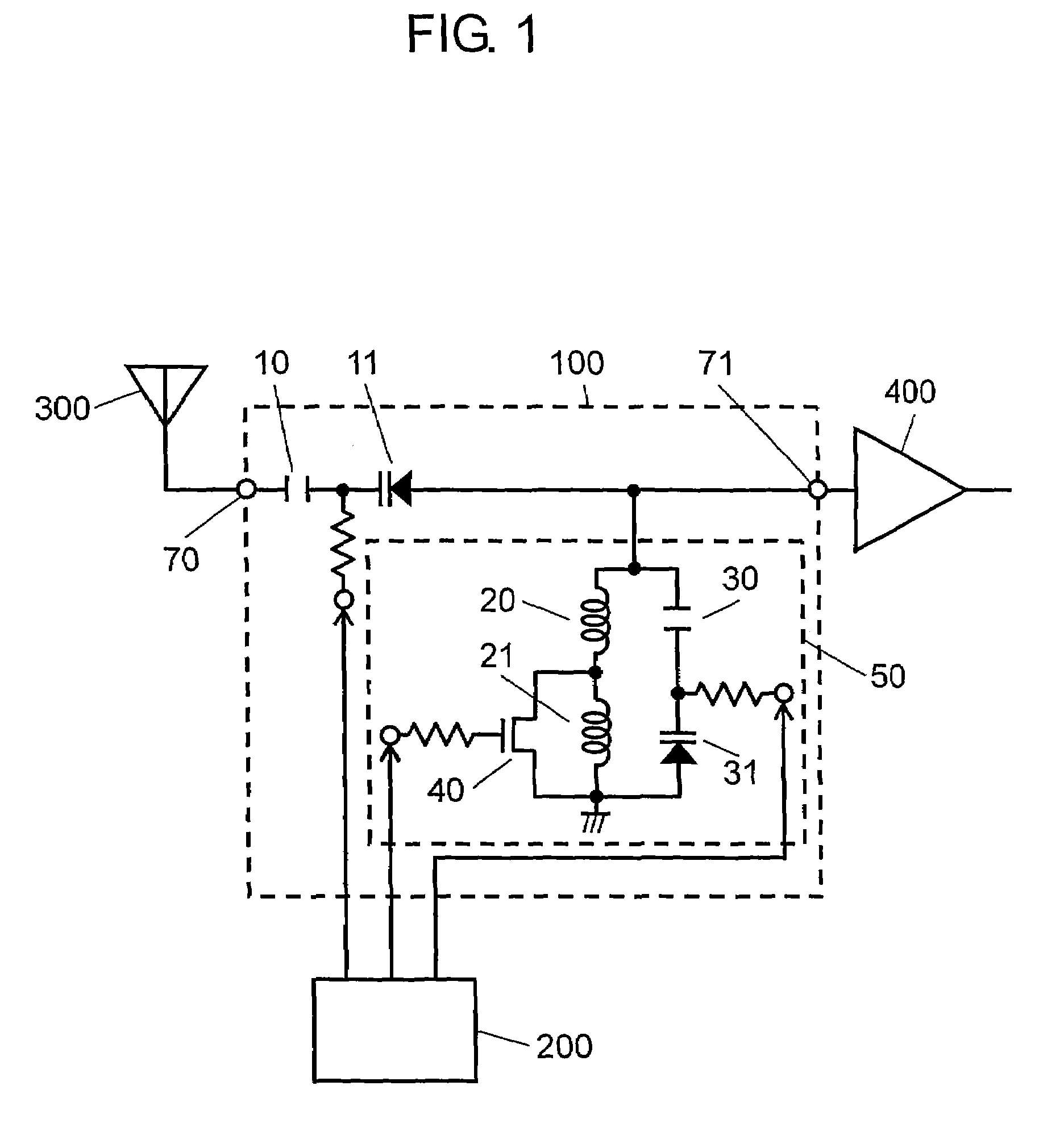
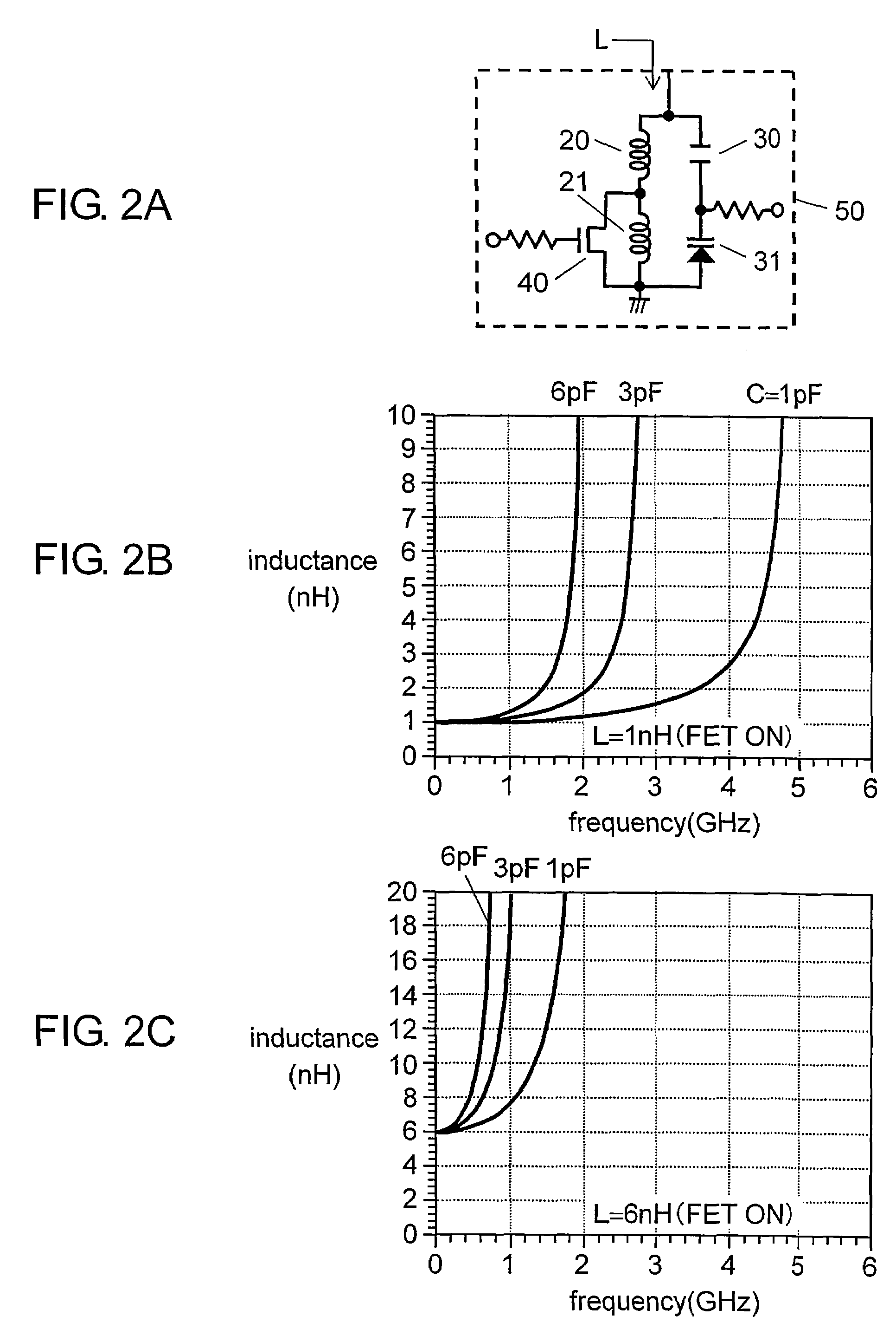
[0051]FIG. 1 shows a structure of a variable matching circuit in accordance with the first embodiment. In FIG. 1, terminals 70 and 71 work as input / output terminals of variable matching circuit 100. Capacitor 10 and varactor diode 11 form a capacitance circuit having a variable capacitance coupled between the foregoing two terminals, and this capacitance circuit forms a second capacitance circuit of the present invention. Resonator-type circuit 50 is grounded via terminal 71, and includes a capacitance circuit formed of capacitor 30 and varactor diode 31, which capacitance circuit corresponds to a first capacitance circuit of the present invention, and an inductance circuit formed of two inductors 20, 21 coupled in series. The capacitance circuit is coupled in parallel to the inductance circuit. Inductors 20, 21 are grounded via FET (field effect transistor) 40. External elements are coupled to variable matching circuit 100 such as varactor diodes 11, 31 and impedance controller 200...
embodiment 2
[0079]FIG. 6 shows a structure of a variable matching circuit in accordance with the second embodiment of the present invention. This structure differs from that shown in FIG. 1 in providing terminals 70 and 71 with first resonator-type circuit 53 and second resonator-type circuit 54 of the present invention respectively. Resonator-type circuits 53 and 54 are schematically shown in FIG. 6 for simple description; however, the actual circuits are similar to resonator-type circuit 50 shown in FIG. 2A and resonator-type circuit 51 or 52 shown in FIG. 4A or FIG. 4B. An operation of circuits 53 and 54 is demonstrated hereinafter, although their basic operation is similar to that described in the first embodiment.
[0080]In FIG. 6, an L-type matching circuit, formed of a seriesly coupled capacitor and a shunt inductor, converts an impedance within a limited range. In this second embodiment, the resonator-type circuits of the present invention are thus provided to both of the input and output...
embodiment 3
[0094]FIG. 8A shows a structure of a variable matching circuit in accordance with the third embodiment. This structure differs from the one shown in FIG. 1 in providing distributed constant line 60 between terminal 71 and resonator-type circuit 55 as well as distributed constant line 61 between terminal 71 and varactor diode 11. Resonator-type circuit 55 shown in FIG. 8A is schematically illustrated for a simple description, but its actual structure is similar to resonator-type circuit 50 shown in FIG. 2A, resonator-type circuit 51 shown in FIG. 4A, or resonator-type circuit 52 shown in FIG. 4B. Resonator-type circuit 55 basically works similarly to the variable matching circuit demonstrated in the first embodiment.
[0095]The variable matching circuit includes the capacitance circuit employing varactor diode 11 and corresponding to the second capacitance circuit of the present invention, so that the capacitance can be varied sequentially. The components to be actually used such as a ...
PUM
 Abstract
Description
Claims
Application Information
 - R&D
- Intellectual Property
- Life Sciences
- Materials
- Tech Scout
- Unparalleled Data Quality
- Higher Quality Content
- 60% Fewer Hallucinations
Browse by: Latest US Patents, China's latest patents, Technical Efficacy Thesaurus, Application Domain, Technology Topic, Popular Technical Reports.
© 2025 PatSnap. All rights reserved.Legal|Privacy policy|Modern Slavery Act Transparency Statement|Sitemap|About US| Contact US: help@patsnap.com


