
Resin infiltration transfer technique

a technology of infiltration transfer and resin, which is applied in the direction of other domestic objects, woodworking apparatuses, chemistry apparatus and processes, etc., can solve the problems of increasing carbon content and reducing the number of viable part processing techniques, and achieve the desired loading level

Inactive Publication Date: 2009-12-08
THE UNITED STATES AS REPRESENTED BY THE DEPARTMENT OF ENERGY
View PDF18 Cites 17 Cited by
  • Summary
  • Abstract
  • Description
  • Claims
  • Application Information

AI Technical Summary

Benefits of technology

[0011]In the present invention, there is provided a novel method for producing a fiber-reinforced composite with a crack-free matrix by utilizing a reaction forming and polymer infiltration and pyrolysis technique. The process involves the interaction of one reactant (e.g, carbon) with a gas or molten metal (e.g., silicon) resulting in complete reaction of two reactants to form one phase. In the case of carbon and silicon, carbon reacts with silicon to form silicon carbide (SiC). The advantages of reaction forming include ease of processing, near-net shape part fabrication, and a reduced number of required processing steps when compared to other conventional ceramic matrix composite fabrication techniques (e.g., chemical vapor infiltration).
[0013]The maximum amount of carbon that can be incorporated into a non-reinforced preform varies from 42.7 volume percent for graphite (p=2.25 g / cm3) to 64.1 volume percent for amorphous carbon (p=1.5 g / cm3). However, care must be taken not to increase the carbon content above a critical limit or the product will form impervious pore channels that choke-off subsequent infiltration of gas or liquid into the remainder of the part. The addition of a high volume of fiber reinforcement and / or particulate reinforcement reduces the number of viable part processing techniques. The high reinforcement volume constrains the part during subsequent processing steps (e.g., curing and pyrolysis) and forces any volumetric changes (e.g., shrinkage) to occur in the matrix regions between the reinforcement.

Problems solved by technology

However, care must be taken not to increase the carbon content above a critical limit or the product will form impervious pore channels that choke-off subsequent infiltration of gas or liquid into the remainder of the part.
The addition of a high volume of fiber reinforcement and / or particulate reinforcement reduces the number of viable part processing techniques.

Method used


Image

  • Resin infiltration transfer technique
  • Resin infiltration transfer technique
  • Resin infiltration transfer technique

Examples


Embodiment Construction

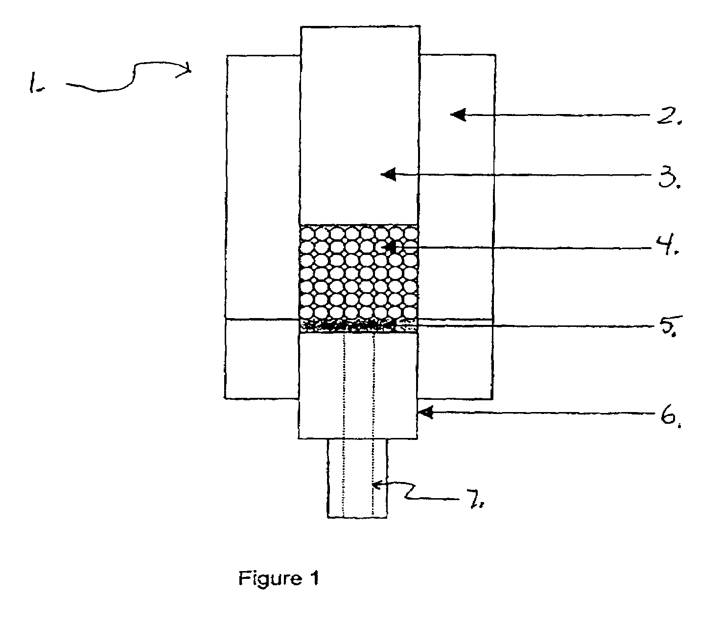
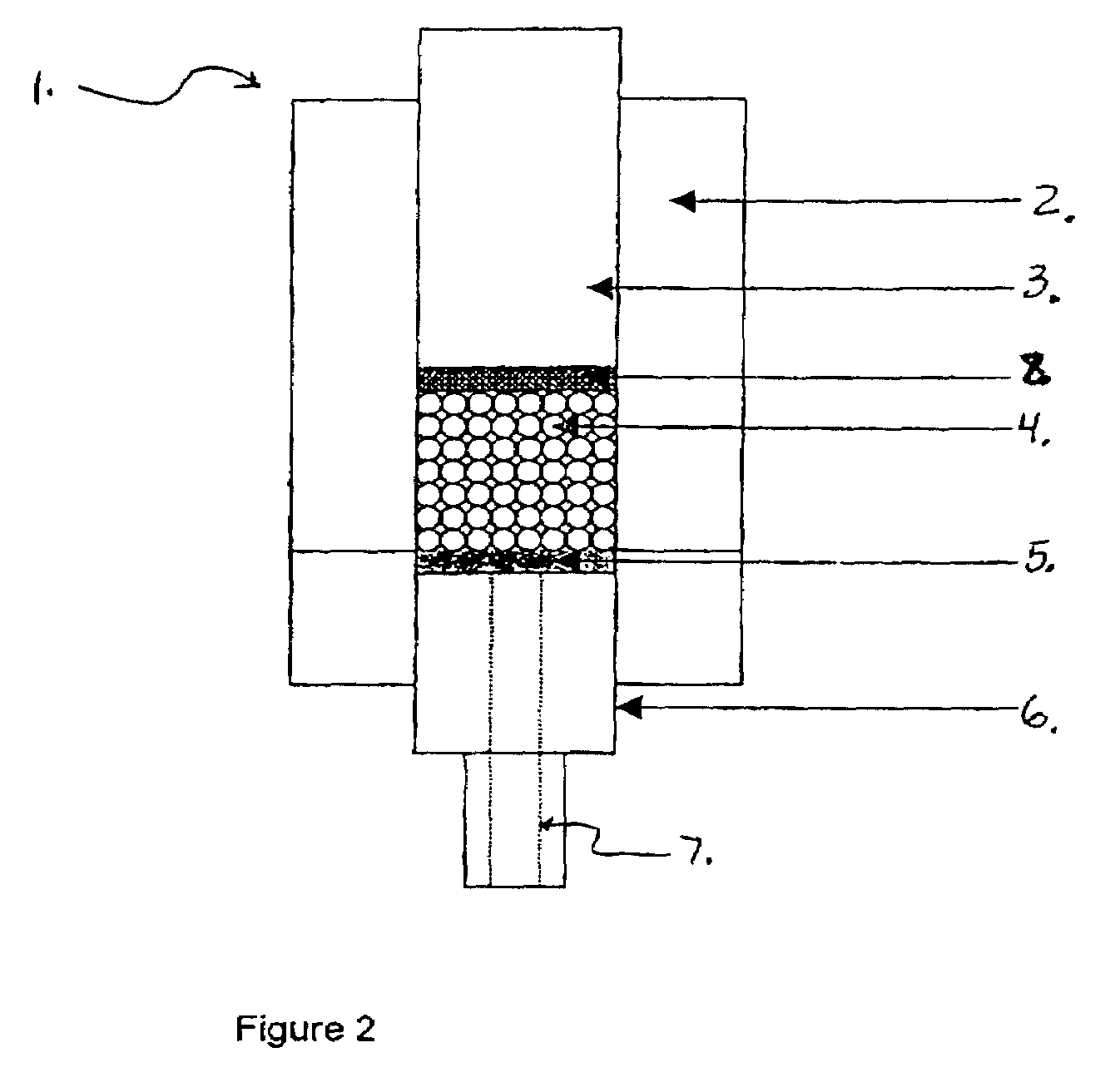
[0020]A preferred embodiment of this invention comprises a process for producing a component with high SiC loading (fiber or particulate) that contains no large Si fissures as currently produced with existing technology. Such fissures result from matrix shrinkage prior to infiltrating the preform with molten silicon. FIG. 1 provides a schematic representation of the mold assembly 1 shown with a reinforcement media 4, a fitting with a hose connection 6, and a hose 7. The mold 1 is shown assembled with a filter 5 at the bottom to retain the reinforcement media 4 and subsequent SiC grit 8 additions in the mold 1. Also, the porous filter 5 provides a means to allow the resin system to wet the mold 1 as discussed in subsequent diagrams. The mold 1 is first loaded with the reinforcement media 4 (fibers or particles) and tapped or vibrated with the weight 3 in place. This allows for maximum packing density of the reinforcement media 4.

[0021]The weight 3 is then removed and SiC grit 8 is ad...


PUM

PropertyMeasurementUnit
Temperatureaaaaaaaaaa
Percent by volumeaaaaaaaaaa

Abstract

A process has been developed for fabricating composite structures using either reaction forming or polymer infiltration and pyrolysis techniques to densify the composite matrix. The matrix and reinforcement materials of choice can include, but are not limited to, silicon carbide (SiC) and zirconium carbide (ZrC). The novel process can be used to fabricate complex, net-shape or near-net shape, high-quality ceramic composites with a crack-free matrix.

Description

STATEMENT REGARDING PRIORITY[0001]This invention claims priority from U.S. Provisional Application No. 60 / 745,539 filed Apr. 25, 2006.CONTRACTUAL ORIGIN OF THE INVENTION[0002]The present invention was conceived and developed under a U.S. Government Contract awarded by the U.S. Department of Energy. The U.S. Government has rights in this invention.BACKGROUND OF THE INVENTION[0003]The present invention relates to Silicon carbide fiber-silicon carbide particulate-reinforced ceramic matrix composites (CMCs) in various high temperature components in nuclear, aerospace and commercial applications.DESCRIPTION OF THE PRIOR ART[0004]Stewart (U.S. Pat. No. 3,969,124) discloses a method for preparing shaped articles of carbon, graphite and mixtures thereof that have low porosity and relatively high bulk density. These shaped carbon and graphite articles are reinforced with reinforcing materials such as fibers and whiskers. The carbon and graphite articles are prepared by combining carbonaceous...

Claims


Application Information

Patent Timeline
IPC IPC(8): C01B31/02
CPCC04B35/5622C04B35/565C04B35/573C04B35/65C04B2235/3826C04B2235/3839C04B2235/80C04B2235/483C04B2235/5427C04B2235/5436C04B2235/5472C04B2235/616C04B2235/404
Inventor MILLER, DAVID V.BARANWAL, RITA
Owner THE UNITED STATES AS REPRESENTED BY THE DEPARTMENT OF ENERGY
Learn More