Constant current zero-voltage switching induction heater driver for variable spray injection
a technology of variable spray injection and heater, which is applied in the direction of fuel injectors, machines/engines, electric control, etc., can solve the problems of high hydrocarbon emissions of conventional spark ignition internal combustion engines, poor fuel ignition and combustibility, and excessive crank tim
- Summary
- Abstract
- Description
- Claims
- Application Information
AI Technical Summary
Benefits of technology
Problems solved by technology
Method used
Image
Examples
embodiment 300
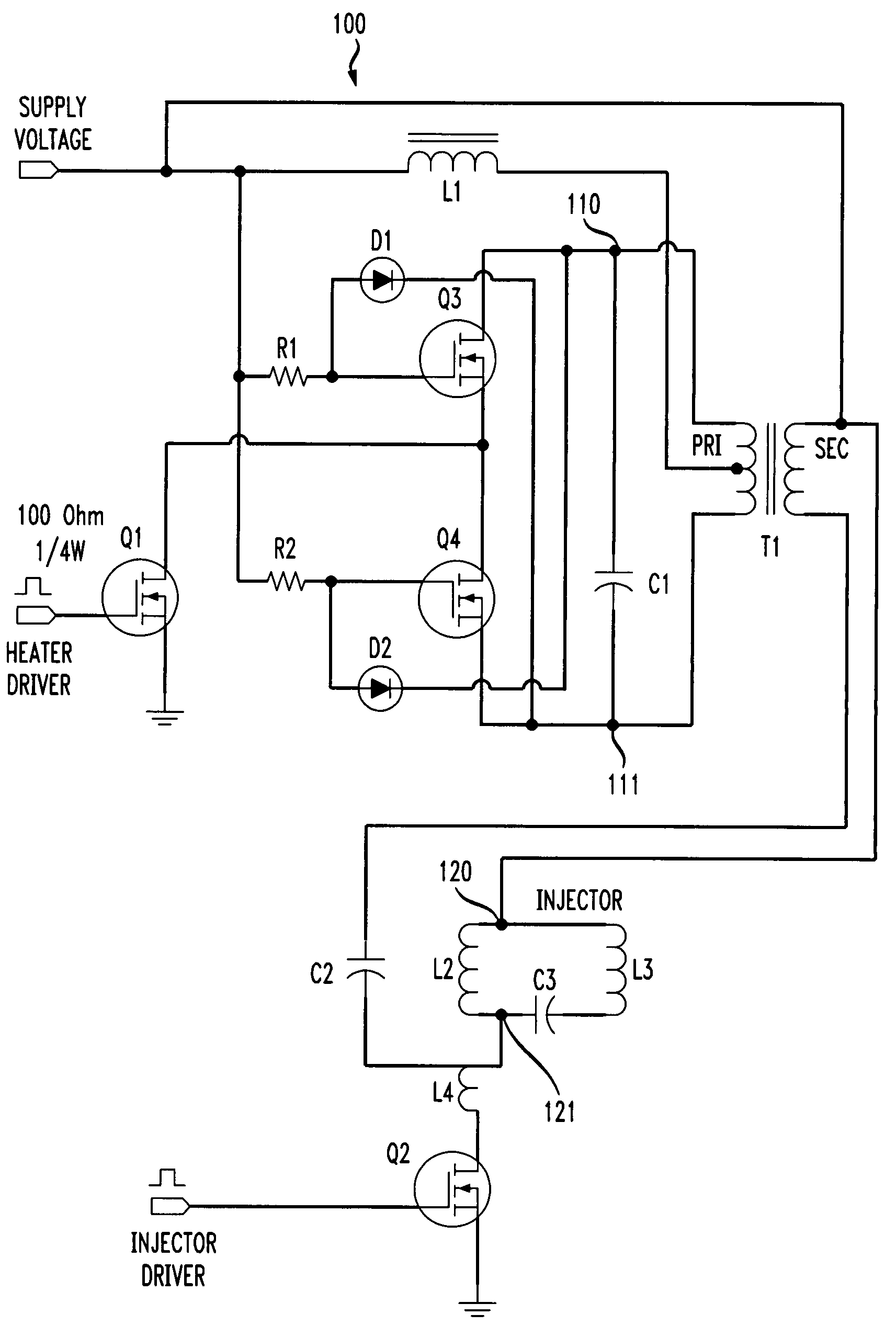
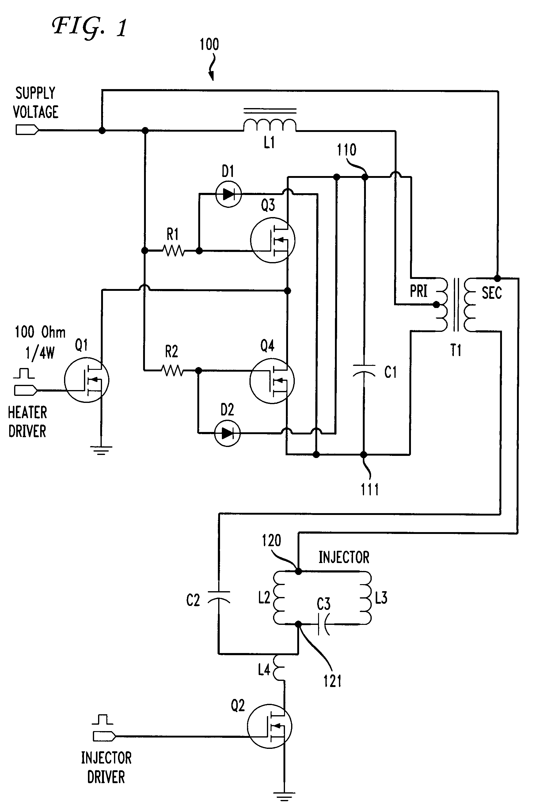
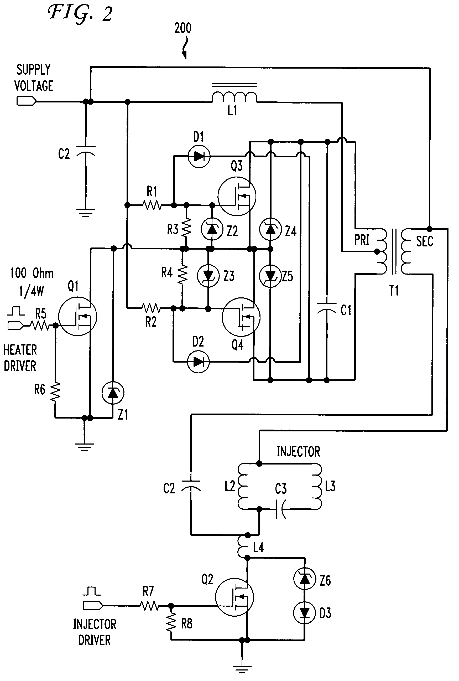
[0062]FIG. 3 depicts an embodiment 300 of the heater driver and injector driver circuit of FIG. 2. Specific component values and specifications are shown in FIG. 3 to illustrate a working prototype. Those values and specifications are merely exemplary and are not intended to limit the scope of the invention.
[0063]The heater driver transformer T1 and the current source inductor L1 may be combined into a hybrid component 400, shown in FIG. 4a. In such a hybrid component, the current source inductor 410 directly taps the high side of the secondary winding 420 of the heater driver transformer for the constant input current.
[0064]The heater driver / injector driver arrangement of the invention may include electromechanical valve actuators other than solenoid actuators. For example, as illustrated in FIG. 4b, a piezoelectric actuator, shown as capacitor 470, may be substituted for the solenoid L2 of FIG. 1. In that case, the piezoelectric actuator 470, together with an inductor 460 in serie...
embodiment 500
[0065]FIG. 5 depicts an alternative embodiment 500 which uses the combined low impedance point, of ground and supply voltage, as the return path for the high frequency alternating current back to T1. That embodiment includes an additional MOSFET switch Q5, enabled when Q1 is enabled, and a high pass filter in the form of an AC bypass capacitor C5 to shunt the high frequency current to ground when Q2 is not turned ‘on.’ The primary disadvantage to that alternative embodiment is that the induction heater must be turned off in a duration window including and prior to the injection driver, Q2, turn-off, otherwise the injection valve closing will be different with the AC bypass capacitor C5 shunting across Q2. Specific component values are shown in FIG. 5 and reflect a working prototype of this embodiment.
[0066]FIG. 6 depicts a gate voltage 610 of Q3 at 5 volts per division, the drain-to-drain voltage 620 across Q3 and Q4 at 25 volts per division, which is the tank voltage, and the heati...
PUM
 Abstract
Description
Claims
Application Information
 - R&D
- Intellectual Property
- Life Sciences
- Materials
- Tech Scout
- Unparalleled Data Quality
- Higher Quality Content
- 60% Fewer Hallucinations
Browse by: Latest US Patents, China's latest patents, Technical Efficacy Thesaurus, Application Domain, Technology Topic, Popular Technical Reports.
© 2025 PatSnap. All rights reserved.Legal|Privacy policy|Modern Slavery Act Transparency Statement|Sitemap|About US| Contact US: help@patsnap.com


