Δσ modulator and δς analog-digital converter
a technology of analog-digital converters and modulators, which is applied in the field of analog-digital converters, can solve the problems of inability to maintain linearity in the wide frequency modulation range, and the modulator of the frequency modulation system has not yet been put into practical use, so as to reduce increase the s/n ratio, and achieve the effect of reducing the requirement of linearity
- Summary
- Abstract
- Description
- Claims
- Application Information
AI Technical Summary
Benefits of technology
Problems solved by technology
Method used
Image


Examples
second embodiment
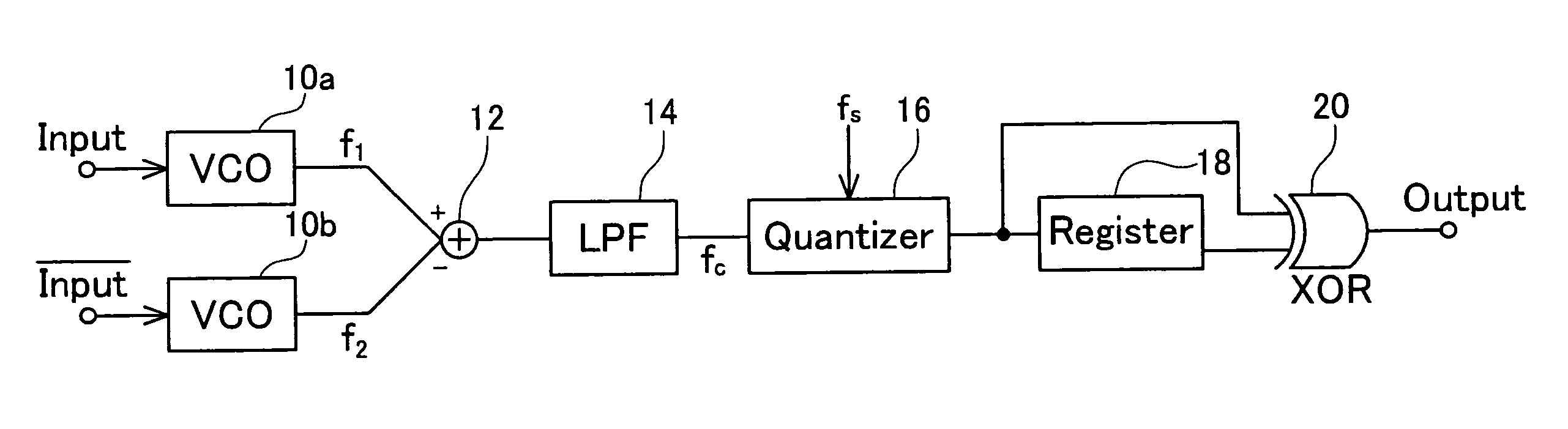
[0119]A description will now be given of a ΔΣ modulator according to a second embodiment of the present invention. FIG. 5 is a block diagram showing a configuration of the ΔΣ modulator according to the second embodiment. As FIG. 5 clearly shows, the ΔΣ modulator according to the second embodiment has a configuration approximately similar to that of the ΔΣ modulator according to the first embodiment, and is different only in frequency modulation signals input to the mixer 12.
[0120]The second embodiment includes two voltage-controlled oscillators 10a and 10b. A signal f1 is obtained by frequency modulation by the voltage-controlled oscillator 10a. A signal f2 is obtained by frequency modulation by the voltage-controlled oscillator 10b. The signal f1 and the signal f2 are mixed by the mixer 12. An analog signal input to the voltage-controlled oscillator 10b is complementary in polarity with respect to an analog signal input to the voltage-controlled oscillator 10a. Therefore, if the si...
third embodiment
[0128]A description will now be given of a ΔΣ modulator according to a third embodiment of the present invention. FIG. 6a shows a configuration of the ΔΣ modulator according to the third embodiment. The ΔΣ modulator according to the third embodiment includes an integrator 22 which receives an analog signal, a first-order ΔΣ modulator 34 connected to the integrator 22, a differential circuit (register 36 and adder 38) connected to the first-order ΔΣ modulator 34, an upper limit detector 24 connected to the integrator 22, and a digital signal processing circuit 40 connected to the differential circuit and the upper limit detector 24.
[0129]The integrator 22 integrates an analog signal input from an input terminal. The analog signal input to the integrator 22 is adjusted so as to be a positive value by adding a proper DC bias voltage. As a result, an output of the integrator 22 monotonically increases as time elapses. Since the output of the integrator 22 monotonically increases, the ou...
fourth embodiment
[0144]A description will now be given of a ΔΣ modulator according to a fourth embodiment of the present invention. FIG. 9 shows a configuration of the ΔΣ modulator according to the fourth embodiment. The ΔΣ modulator according to the fourth embodiment is a so-called MASH type ΔΣ modulator. This ΔΣ modulator includes a ΔΣ modulator (42, 44, 46, 48) on a first stage, and a ΔΣ modulator 54 on a second stage.
[0145]The ΔΣ modulator on the first stage is a ΔΣ modulator of feedback system. In other words, the ΔΣ modulator on the first stage includes an integrator 44 which integrates an input signal, a quantizer 46 which quantizes an output of the integrator 44, a digital-analog converter 48 which converts a digital output of the quantizer 46 into an analog signal, and an adder 42 which inverts the polarity of the analog signal converted by the digital-analog converter 114 and adds the inverted analog signal to the input analog signal.
[0146]The ΔΣ modulator on the first stage is connected t...
PUM
 Abstract
Description
Claims
Application Information
 - R&D
- Intellectual Property
- Life Sciences
- Materials
- Tech Scout
- Unparalleled Data Quality
- Higher Quality Content
- 60% Fewer Hallucinations
Browse by: Latest US Patents, China's latest patents, Technical Efficacy Thesaurus, Application Domain, Technology Topic, Popular Technical Reports.
© 2025 PatSnap. All rights reserved.Legal|Privacy policy|Modern Slavery Act Transparency Statement|Sitemap|About US| Contact US: help@patsnap.com