Eureka AIR delivers breakthrough ideas for toughest innovation challenges, trusted by R&D personnel around the world.

Construction machine and method of controlling construction machine

a construction machine and construction method technology, applied in the field of construction machines, can solve problems such as the inoperative system of the hybrid vehicle, and achieve the effects of reducing the load on the electric device, reducing the temperature of the electric device, and narrowing the range of engine speed variation

Inactive Publication Date: 2010-02-11
KOMATSU LTD
View PDF3 Cites 34 Cited by
  • Summary
  • Abstract
  • Description
  • Claims
  • Application Information

AI Technical Summary

Benefits of technology

[0013]According to the invention, the engine minimum speed in carrying out the low-speed matching increases or is the constant value as the temperatures of the electric devices increase and therefore a range of variation in the engine speed is narrowed and loads on the electric devices are reduced. As a result, increase in the temperatures of the electric devices can be suppressed. Consequently, overheating of the mounted electric devices can be prevented properly with a simple structure without relying on increase in capacitance of the storage device.

Problems solved by technology

If these electric devices accumulate excessive heat, they may become damaged to make a system of the hybrid vehicle inoperative.

Method used


Image

  • Construction machine and method of controlling construction machine
  • Construction machine and method of controlling construction machine
  • Construction machine and method of controlling construction machine

Examples


Embodiment Construction

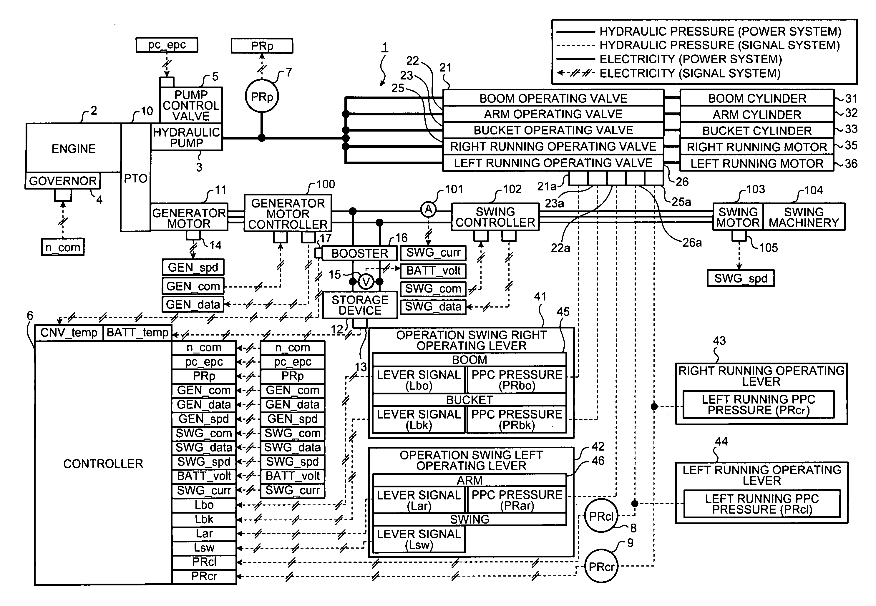
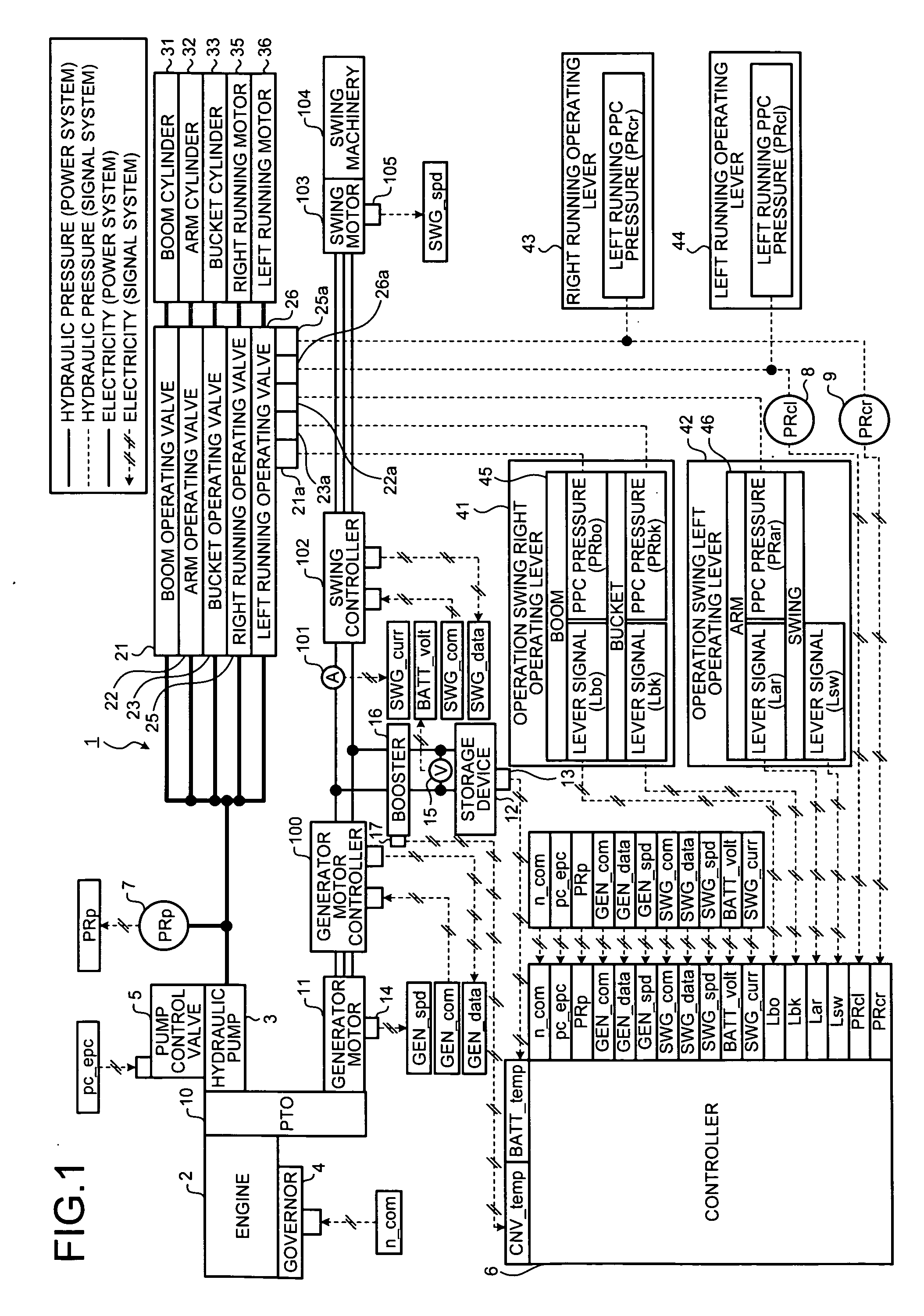
[0056]A best mode (hereafter referred to as “embodiment”) for carrying out the present invention will be described below with reference to the accompanying drawings. FIG. 1 is a drawing showing a general structure of a construction machine according to the embodiment of the invention. In the present embodiment, a construction machine is a hydraulic shovel having an excavating function.

[0057]FIG. 2 is a drawing showing an external structure of the hydraulic shovel. The hydraulic shovel 1 shown in the drawing includes a running body 201 and a swing body 202. The running body 201 is made up of left and right crawler tracks. On the swing body 202, an operating machine made up of a boom 203, an arm 204, and a bucket 205 is mounted.

[0058]In the hydraulic shovel 1, a boom cylinder 31 is driven to actuate the boom 203, an arm cylinder 32 is driven to actuate the arm 204, and a bucket cylinder 33 is driven to actuate the bucket 205. A right running motor 35 and a left running motor 36 are dr...


PUM


Abstract

The present invention provides a construction machine where overheating of mounted electric devices can be prevented properly with a simple structure and a method of controlling the construction machine. For this purpose, a pump target discharge flow rate of a hydraulic pump is calculated based on an operated amount of an operating unit, a temperature of an electric device mounted on the construction machine is detected, an engine minimum speed, which is a minimum possible speed of an engine in carrying out low-speed matching for matching output of the engine and pump absorbing horsepower of the hydraulic pump to each other in a low-speed region where speed of the engine is lower than set speed, is calculated by using the detected temperature of the electric device, and a maximum value out of a corresponding speed of the pump target discharge flow rate and the engine minimum speed is generated as a candidate for an engine target speed.

Description

TECHNICAL FIELD[0001]The present invention relates to a construction machine including an engine and a generator motor coupled to each other as drive sources and a hydraulic pump driven by the engine and the generator motor and a method of controlling the construction machine.BACKGROUND TECHNIQUE[0002]Conventionally, a hybrid vehicle using an engine and a generator motor coupled to each other as drive sources includes electric devices such as a storage device for giving and receiving electric power to and from the generator motor, a booster for boosting voltage of the storage device, and an inverter for driving the generator motor. If these electric devices accumulate excessive heat, they may become damaged to make a system of the hybrid vehicle inoperative. To solve this problem, a technique for preventing overheating of the electric devices by properly cooling the electric devices provided to the hybrid vehicle is disclosed (see Patent Document 1, for example).[0003]Patent Documen...

Claims


Application Information

Patent Timeline
IPC IPC(8): F16D31/02B60W20/00B60L50/16
CPCB60L1/003Y02T10/70B60L3/06B60L11/14B60L11/187B60L11/1872B60L2240/36B60W2510/246B60W2710/0644B60Y2200/412E02F9/2025F02D29/02Y02T10/7005Y02T10/705Y02T10/7077B60L3/0046E02F9/2075E02F9/2246E02F9/2091B60L50/16B60L58/24B60L58/25Y02T10/7072B60W2510/244E02F9/20B60K6/485B60W10/06
Inventor MORINAGA, JUNINOUE, HIROAKIKAWAGUCHI, TADASHI
Owner KOMATSU LTD
Why Eureka
Eureka Blog
Learn More