
High strength-to-weight-ratio slickline and multiline cables

a technology of slickline cables and multi-line cables, applied in the direction of cables, insulated conductors, instruments, etc., can solve the problems of reducing data carrying capacity, hydrolytic attack on glass in the presence of water, and oilfield operations are vulnerable to damage,

Active Publication Date: 2009-10-13
SCHLUMBERGER TECH CORP
View PDF19 Cites 64 Cited by
  • Summary
  • Abstract
  • Description
  • Claims
  • Application Information

AI Technical Summary

Benefits of technology

The present invention relates to slickline cables and methods for manufacturing them. The invention includes a polymer composite rod with a channel for housing an optical fiber, which is secured using a polymer tape, layer, or combination of both. An outer tube is then placed over the polymer composite rod to protect the optical fiber. The technical effects of this invention include improved durability and reliability of the slickline cables, as well as increased efficiency in the manufacturing process.

Problems solved by technology

Unfortunately, this potential is offset by several weaknesses that make them vulnerable to damage in oilfield operations.
For example, exposure to hydrogen at high temperatures results in darkening of the optical fiber which leads to a reduction in data carrying capacity.
Hydrolytic attack against glass in the presence of water is yet another source of damage.
Furthermore, linear stretch of the fiber is limited when compared to the other cable components.
This requires additional fiber length in the optical fiber components, which complicates the manufacturing process.
A lack of transverse toughness of the fiber component construction can result in potential point loading and micro-bending issues.
These can lead to mechanical failure of the fiber and / or signal attenuation.
Several problems have been encountered with this design.
In addition, different materials used in the slickline cable may have different coefficients of thermal expansion, which may cause some problems.
During pultrusion and curing of the composite, the optical fiber is subjected to curing temperatures between 400 to 500° F. for a short period of time, which can damage the fiber's polymer coating.
Also, the fiber finish of the composite may interfere with the epoxy curing.
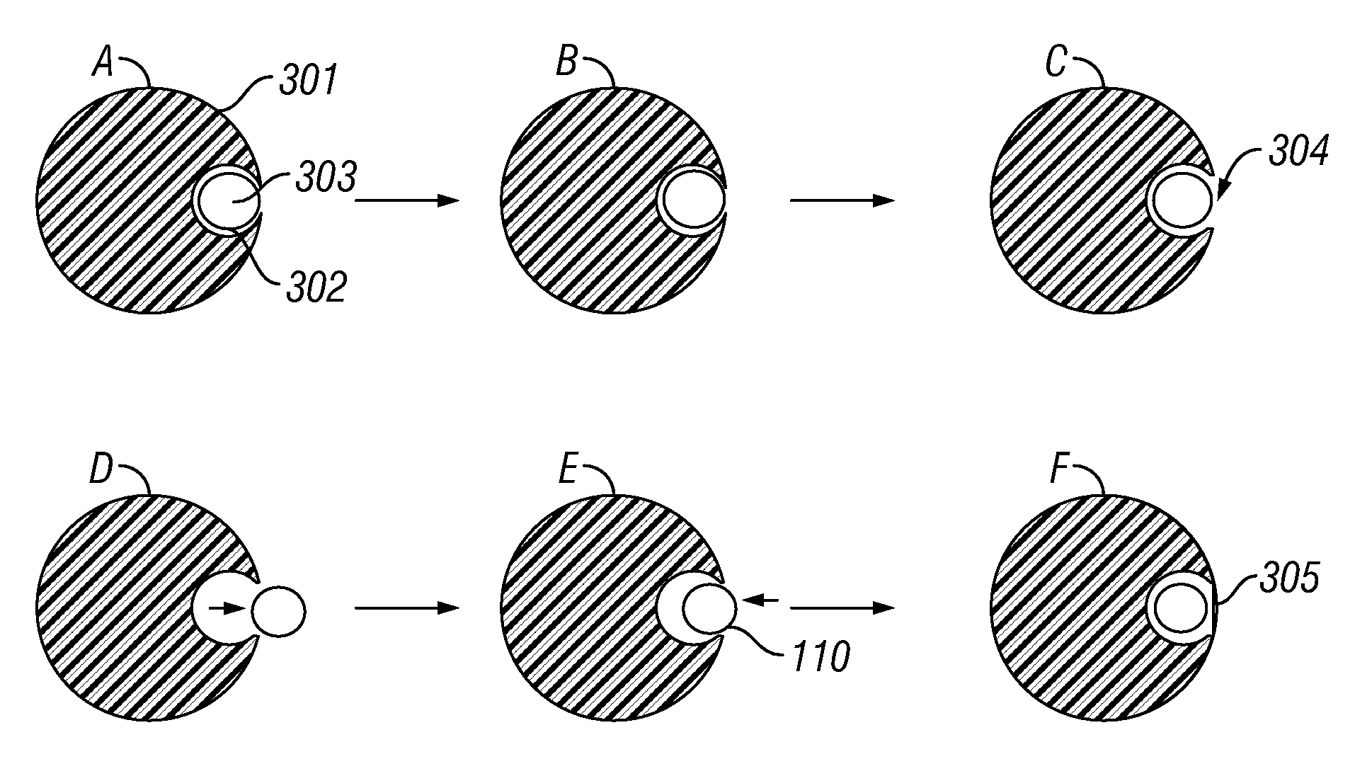
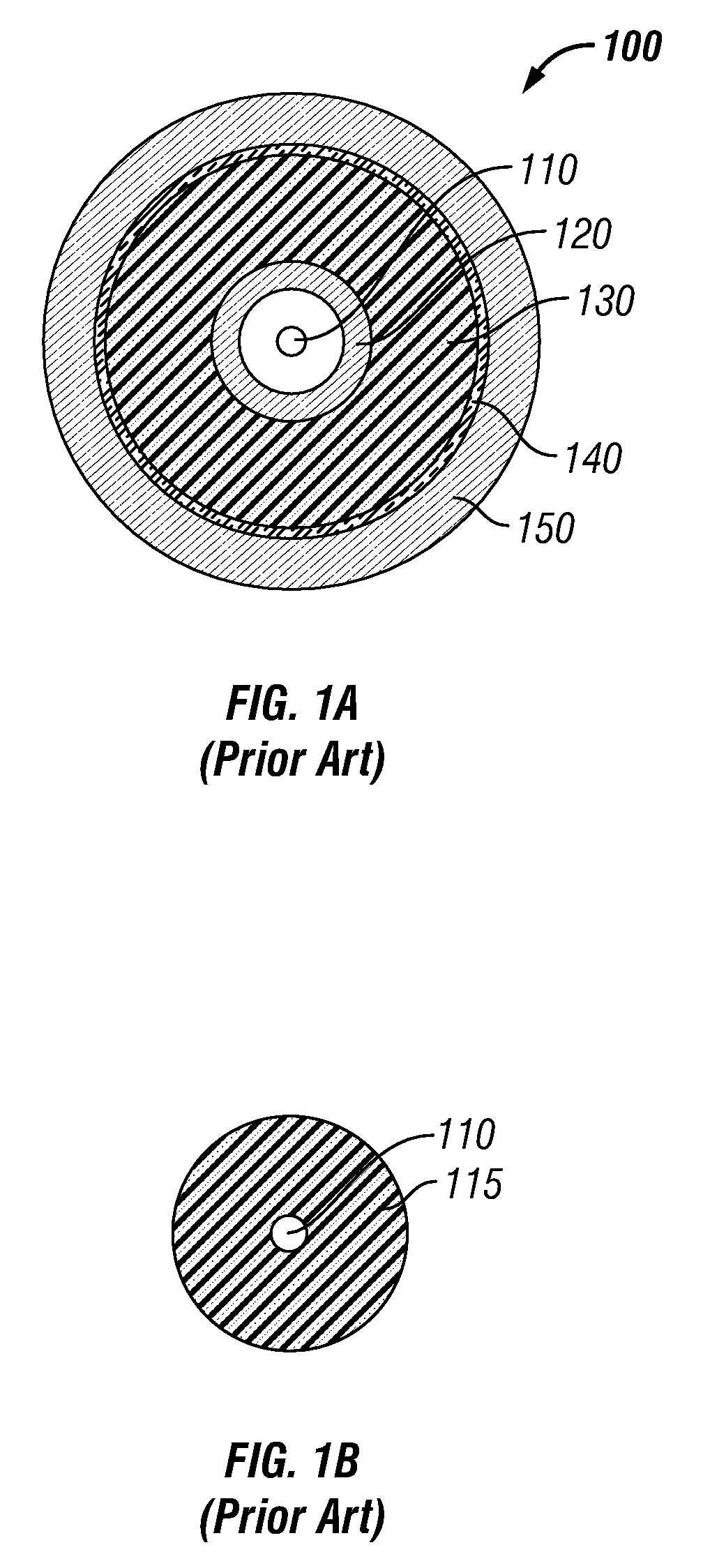
Although a fiber optic as shown in FIG. 1B is more robust, the processes of covering the fiber optics with the composite resin jackets may lead to some problems.
For example, high loss of optical fiber can occur due to point loading in the pultrusion process.
Shrinkage that occurs as the epoxy cures can impinge on the optical fiber and create signal attenuation problems.
The need to handle the optical fibers carefully in order to reduce the likelihood of point loading and overpull in the pultrusion process makes manufacturing difficult and time-consuming.
The high incidence of signal attenuation encountered with these fiber optic components is unacceptable for use in oilfield distributed temperature system measurements and in applications requiring long-length telemetry.

Method used


Image

  • High strength-to-weight-ratio slickline and multiline cables
  • High strength-to-weight-ratio slickline and multiline cables
  • High strength-to-weight-ratio slickline and multiline cables

Examples


Embodiment Construction

[0034]The foregoing disclosure and description of the invention is illustrative and explanatory thereof and it can be readily appreciated by those skilled in the art that various changes in the size, shape and materials, as well as in the details of the illustrated construction or combinations of the elements described herein can be made without departing from the spirit of the invention. In addition, the cables can also comprise some components other than the ones already cited. In the summary of the invention and this detailed description, each numerical value should be read once as modified by the term “about” (unless already expressly so modified), and then read again as not so modified unless otherwise indicated in context.

[0035]Embodiments of the present invention relate to slickline cables, particularly slickline cables that have high strength-to-weight ratios, and processes for making such cables. To avoid exposure of optical fibers to high temperatures during the manufactur...


PUM


Abstract

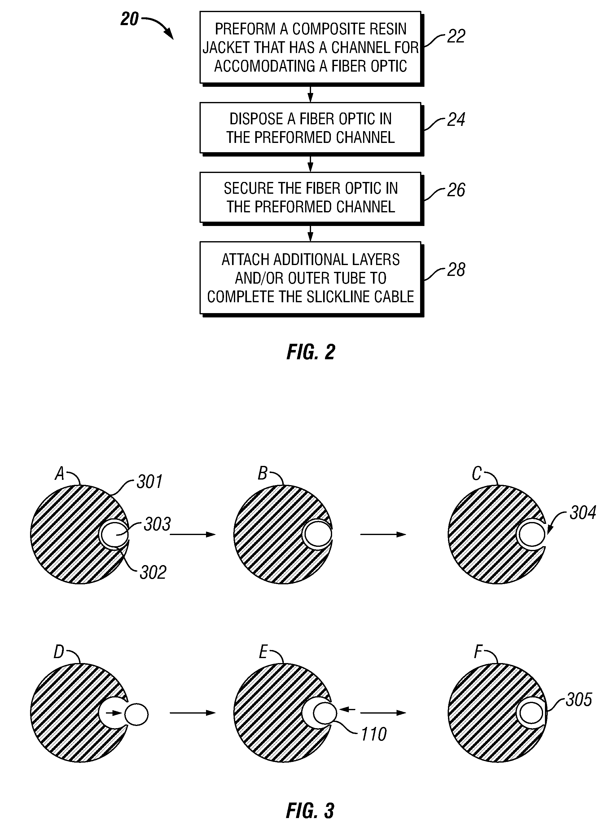
Slickline cables and methods for preparing such cables are disclosed. A slickline cable includes a pre-manufactured polymer composite rod having a channel therein; an optical fiber disposed in the channel; a fastener securing the optical fiber in the channel, wherein the fastener is selected from the group comprising a polymer tape, a polymer layer, and a combination thereof, and an outer tube disposed outside the polymer composite rod having the optical fiber therein. A method for manufacturing a slickline cable includes preparing a polymer composite rod having at least one channel therein; placing at least one optical fiber in the at least one channel in the polymer composite rod; securing the at least one optical fiber in the at least one channel using a polymer tape, a polymer layer, or a combination of a polymer tape and a polymer layer; disposing an outer tube over the polymer composite rod.

Description

BACKGROUND OF INVENTION[0001]1. Field of the Invention[0002]The invention relates generally slickline cables used in oilfield operations.[0003]2. Background Art[0004]Fiber optic components in wireline or permanent monitoring cables have a great potential for data transfer applications. Unfortunately, this potential is offset by several weaknesses that make them vulnerable to damage in oilfield operations. For example, exposure to hydrogen at high temperatures results in darkening of the optical fiber which leads to a reduction in data carrying capacity. Evaporation of volatile organic compounds (VOCs) in coatings or other polymeric protective layers on the optical fibers releases hydrogen, which can attack and darken the fiber. Hydrolytic attack against glass in the presence of water is yet another source of damage.[0005]Furthermore, linear stretch of the fiber is limited when compared to the other cable components. This requires additional fiber length in the optical fiber componen...

Claims


Application Information

Patent Timeline
Patent Type & Authority Patents(United States)
IPC IPC(8): G02B6/44
CPCG02B6/4486H01B13/18H01B11/22H01B7/0208G02B6/4488
Inventor VARKEY, JOSEPHSINGH, ANILKIM, BYONG JUNHERNANDEZ, VLADIMIRNIMCHAN, SHANNONTABALAN, DAN
Owner SCHLUMBERGER TECH CORP
Learn More