Printer and adhesive label manufacturing device

a printing device and printing technology, applied in the field of printing machines, can solve the problems of deteriorating efficiency with which adhesive labels are produced, failure of conveying, and inconvenient use of adhesive labels produced and discharged from printers, and achieve the effect of smooth deflecting a heat-sensitive adhesive sheet and easy cutting of heat-sensitive adhesive sheets

Inactive Publication Date: 2009-10-13
SEIKO INSTR INC
View PDF6 Cites 6 Cited by
  • Summary
  • Abstract
  • Description
  • Claims
  • Application Information

AI Technical Summary

Benefits of technology

[0012]Therefore, the objectives of 'the present invention are to provide a printer that can smoothly deflect a heat-sensitive adhesive sheet in a direction that matches a direction in which the heat-sensitive adhesive sheet is wound around a roll member, and can easily cut the heat-sensitive adhesive sheet to predetermined lengths, and a method for manufacturing an adhesive label.
[0021]According to this arrangement, since the heat-sensitive adhesive sheet can be cut before the sheet enters the thermal activation device, a defect, such as a jam caused by the heat-sensitive adhesive sheet sticking to the thermal activation device, can be prevented, no maintenance is required to remove the jam, and the efficiency for producing adhesive labels can be considerably improved. Furthermore, according to this arrangement, the heat-sensitive adhesive sheet is deflected downward, forming a concave shape, in order for the sheet to be cut to a predetermined length. Therefore, the heat-sensitive adhesive sheet can be easily and smoothly deflected in consequence with the direction in which the sheet is wound.
[0024]The printing device includes: a heater, used for printing, for contacting and heating the printing enabled layer; and a first conveying unit for conveying the heat-sensitive adhesive sheet. The thermal activation device includes: a heater, used for thermal activation, for contacting and heating the heat-sensitive adhesive layer, and a second conveying unit for conveying the heat-sensitive adhesive sheet. By controlling the second conveying unit and the first conveying unit speeds, the heat-sensitive adhesive sheet can be deflected downward to form a concave shape at the guide portion. With this arrangement, the heat-sensitive adhesive sheet can be deflected very easily, and a length to be cut can be accurately designated.
[0032]According to this method, since the heat-sensitive adhesive sheet can be deflected downward to form a concave shape and be cut to a predetermined length, smooth deflection of the sheet, in consonance with the direction in which the heat-sensitive adhesive sheet is wound, can be easily performed.
[0035]According to the present invention, when a heat-sensitive adhesive sheet that is wound in a different direction from the conventional is employed, the sheet can be easily and smoothly deflected. Therefore, a desired adhesive label can be easily produced by adjusting the length of the heat-sensitive adhesive sheet, and the manufacturing efficiency can be increased.

Problems solved by technology

Thus, when sheet feeding is resumed after the cutting has been completed and a label has been produced, the heat-sensitive adhesive sheet 100 is not fed smoothly, and a so-called jam occurs, one which in turn causes a conveying failure.
An adhesive label that is thus produced and discharged from the printer is not appropriate for use because its appearance is not pleasing.
Thus, as described above, the efficiency with which adhesive labels are produced is deteriorated.
However, the printing enabled layer 100b is the surface on which characters, symbols, numbers or images are represented when an adhesive label is completed, and on this surface, smudging is not desirable.
As a result, adhesive labels of the desired lengths can not be produced, the manufacturing accuracy is very low, and deterioration of the production yield occurs.

Method used


Image

  • Printer and adhesive label manufacturing device
  • Printer and adhesive label manufacturing device
  • Printer and adhesive label manufacturing device

Examples


Embodiment Construction

[0043]The preferred embodiment of the present invention will now be described while referring to the accompanying drawings.

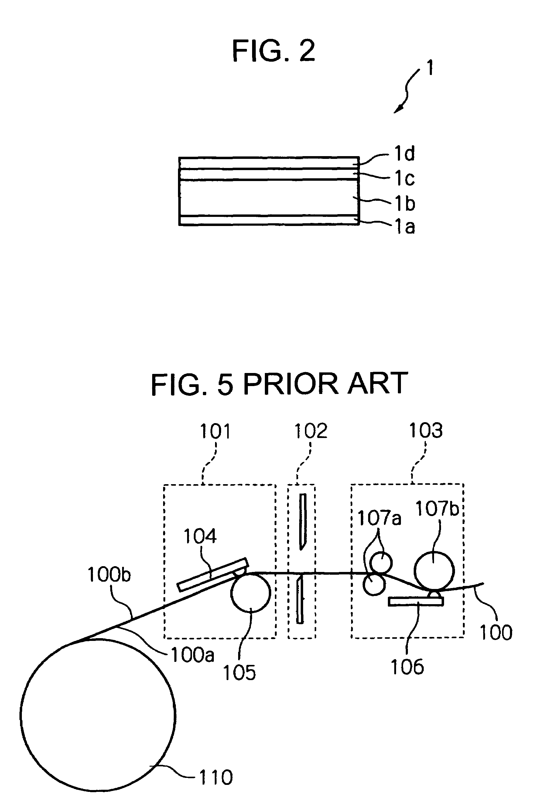
[0044]FIG. 1 is a schematic cross-sectional view of the internal configuration of a printer according to the present invention for manufacturing adhesive labels based on a heat-sensitive adhesive sheet. The basic configuration of the printer using a heat-sensitive adhesive sheet will be briefly explained. This printer includes: a roll member storage unit 2, for holding a roll member 11 formed by winding around it a heat-sensitive adhesive sheet 1; a printing device 3, for printing on a printing enabled layer 1d (see FIG. 2) of the heat-sensitive adhesive sheet 1; a cutter device 4, for cutting the heat-sensitive adhesive sheet 1 to a predetermined length; a thermal activation device 5, for thermally activating a heat-sensitive adhesive layer 1a (see FIG. 2) of the heat-sensitive adhesive sheet 1; and a guide portion 6, for guiding the heat-sensitive adhesive she...


PUM

PropertyMeasurementUnit
heat-sensitiveaaaaaaaaaa
lengthaaaaaaaaaa
speedsaaaaaaaaaa

Abstract

A heat-sensitive adhesive sheet is inserted into a printing device and heated by a thermal head to perform printing on a printable layer of the sheet. After printing, the heat-sensitive adhesive sheet is conveyed forward until the leading edge of the sheet abuts upon a guide roof member. While contacting the guide roof member, the leading edge of the heat-sensitive adhesive sheet is slid down and guided along the guide roof member to the nip portion of a pair of insertion rollers and is held at the nip. Once the insertion rollers have been halted, or have begun rotating slowly, the heat-sensitive adhesive sheet is conveyed further and deflected downward and assumes a concave shape. Then, the heat-sensitive adhesive sheet is cut to a predetermined length by a cutting device, and the heat-sensitive adhesive layer of the cut portion is heated and thermally activated by a thermal activation device.

Description

BACKGROUND OF THE INVENTION[0001]1. Field of the Invention[0002]The present invention relates to a printer that employs a heat-sensitive adhesive sheet, wherein a heat-sensitive adhesive layer, which normally is not adhesive but becomes adhesive when thermally activated, is deposited on one face of a sheet base material, and produces an adhesive label that has desired characters, symbols, numbers or images recorded on the obverse face and adhesive on the reverse face, and relates to a method for producing such an adhesive label.[0003]2. Description of the Related Art[0004]Conventionally, as disclosed in Japanese Patent Laid-Open Publication No. Hei 11-79152, a heat-sensitive adhesive sheet having a heat-sensitive adhesive layer that becomes adhesive when heated has been put to practical use. The heat-sensitive adhesive sheet has several advantages, such as that handling the sheet before it is heated is easy and that no industrial waste is generated because release paper is not requi...

Claims


Application Information

Patent Timeline
Patent Type & Authority Patents(United States)
IPC IPC(8): B32B37/00
CPCB41J3/4075B41J15/046B65C9/25Y10T156/1052Y10T156/12Y10T156/1085B65C2009/0081
Inventor TAKAHASHI, MASANORI
Owner SEIKO INSTR INC
Why Eureka
Try Eureka