
Tension leg platform model mooring device

A tension leg platform and mooring device technology, which is applied in transportation and packaging, ship parts, ships, etc., can solve the problems of tension leg deflection limitation, large rotational friction force, small rotational friction force, etc., to achieve optimal load capacity, The effect of large deflection angle and uniform bearing

Active Publication Date: 2017-03-29
SHANGHAI JIAO TONG UNIV
View PDF7 Cites 1 Cited by
  • Summary
  • Abstract
  • Description
  • Claims
  • Application Information

AI Technical Summary

Problems solved by technology

In order to comprehensively consider the loads in different directions of the ocean, the following issues need to be considered in the test simulation: under the action of external loads, due to the action of ocean currents in different directions, the tension leg structure of the tension leg platform will bear loads in different directions. The mooring cable connection method may limit the deflection of the tension leg, thereby affecting the accuracy of the test
[0005] At the same time, under the condition of high tension, there is no base on the market that can rotate freely with multiple degrees of freedom. In the past, universal joints were used instead, but the friction force of the universal joint is very large when it rotates under the action of high tension, which seriously affects the test. quality
Moreover, most of the existing bearings have relatively large rotational friction under high pressure, and none of them can solve the technical problem of ensuring small rotational friction under high tension

Method used


Image

  • Tension leg platform model mooring device
  • Tension leg platform model mooring device
  • Tension leg platform model mooring device

Examples


Embodiment Construction

[0022] The preferred embodiments of the present invention will be described in detail below in conjunction with the accompanying drawings, so that the advantages and features of the present invention can be more easily understood by those skilled in the art, so as to define the protection scope of the present invention more clearly.

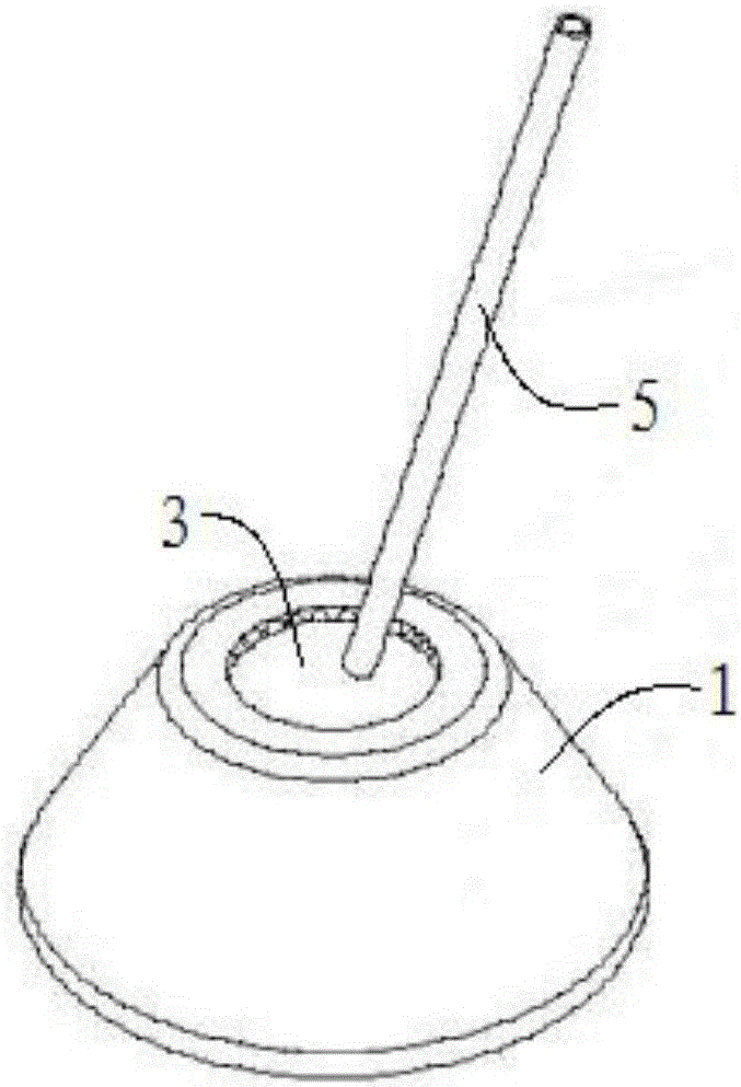
[0023] refer to Figure 1-3 Shown, the tension leg platform model mooring device of the present invention, it comprises:

[0024] The base 1 is fixed on the bottom of the sea, and the inside of the base 1 is provided with an open cavity 2, and the inside of the open cavity 2 is provided with a rotating sphere 3, and the outer surface of the rotating sphere 3 and the inner wall of the open cavity 2 pass through multiple The bearing steel balls 4 are interconnected; the rotating sphere 3 in the present invention is a rotating steel ball, which can ensure sufficient rigidity and improve the reliability and stability of use, and the shape of the open...


PUM


Abstract

The invention discloses a tension leg platform model mooring device which comprises a foundation support and a tension leg. The foundation support is fixed to the sea floor. An opening cavity is formed in the foundation support. A rotating sphere is arranged in the opening cavity. The outer surface of the rotating sphere and the inner wall of the opening cavity are connected with each other through multiple bearing steel balls. The tension leg comprises multiple tension leg single bodies. The end portions of every two adjacent tension leg single bodies are connected through elastic connecting pieces, the lower end of the lowest tension leg single body is connected with the rotating sphere, and the higher end of the highest tension leg single body is connected with an external platform model body. The device is not restricted by the traditional tension leg deflection angle any more, and then the more accurate testing result is obtained. Meanwhile, bearing of each tension leg single body is more uniform, and the problems that a traditional tension leg structure bears too heavy loads and the requirement for materials is high are optimized.

Description

technical field [0001] The invention relates to the technical field of ships and ocean engineering, in particular to a model mooring device for a tension leg platform. Background technique [0002] Tension leg platform is an important engineering facility and equipment for offshore oil and gas development. The construction and optimization of tension leg platforms play a vital role in the development of offshore oil and gas resources, national economic construction and energy utilization. [0003] During the construction of the TLP, it is necessary to consider the material selection of the TLS, the connection method between the TLS and the seabed mooring device, etc. The characteristic of the tension leg platform is that the buoyancy generated by itself is much greater than the gravity, and the remaining buoyancy needs to be balanced with the pretension. The effect of pre-tension on the tension leg requires in-depth consideration of materials and connection methods in the ...

Claims


Application Information

Patent Timeline
Patent Type & Authority Applications(China)
IPC IPC(8): B63B21/50B63B35/44
CPCB63B21/502B63B35/4406B63B2021/501
Inventor 吕海宁卢文月郭孝先赵国成石城
Owner SHANGHAI JIAO TONG UNIV
Learn More