Optimized gain filtering technique with noise shaping

a gain filtering and noise shaping technology, applied in pulse manipulation, pulse technique, frequency selective two-port network, etc., can solve the problems of inability to optimize gain filtering, and inability to achieve noise shaping effect,

Active Publication Date: 2009-09-22
ATMEL CORP
View PDF10 Cites 3 Cited by
  • Summary
  • Abstract
  • Description
  • Claims
  • Application Information

AI Technical Summary

Problems solved by technology

However both techniques tend to suffer from a limited noise performance.
Hence, to achieve an acceptable post down-conversion mixer low noise filter topology using those techniques leads to an unacceptable power and chip area penalties.
The disadvantages of these techniques are: (1) higher noise that prevents higher order filters from being used in low noise application (such as a post-mixer amplifier in a wireless integrated receiver); (2) high linearity demands on the amplifiers used, especially the amplifier preceding the first filter stage; (3) larger chip area and power consumption are required to achieve a high dynamic range; and (4) the filter circuitry is in the signal path and hence contributes to degrading noise, offset, and matching.
The problem facing integrated wireless receivers is that RF front-ends do not have any selectivity and hence the entire filtering operation should be performed at baseband.
The RF section also can only provide a limited gain to the desired signal (due to the existence of blockers).
However, this places a stringent noise requirement on the filter used.
Hence, the overall dynamic range is limited either by linearity or by noise.
Therefore, implementing higher dynamic range filters / amplifiers leads to more power consumption and larger die area. FIG. 2(C) shows a gain filter interleaved stages.
Nevertheless, the first gain stage and first amplification stage in this topology are still going to be challenging.

Method used


Image

  • Optimized gain filtering technique with noise shaping
  • Optimized gain filtering technique with noise shaping
  • Optimized gain filtering technique with noise shaping

Examples


Embodiment Construction

[0026]The embodiments herein and the various features and advantageous details thereof are explained more fully with reference to the non-limiting embodiments that are illustrated in the accompanying drawings and detailed in the following description. Descriptions of well-known components and processing techniques are omitted so as to not unnecessarily obscure the embodiments herein. The examples used herein are intended merely to facilitate an understanding of ways in which the embodiments herein may be practiced and to further enable those of skill in the art to practice the embodiments herein. Accordingly, the examples should not be construed as limiting the scope of the embodiments herein.

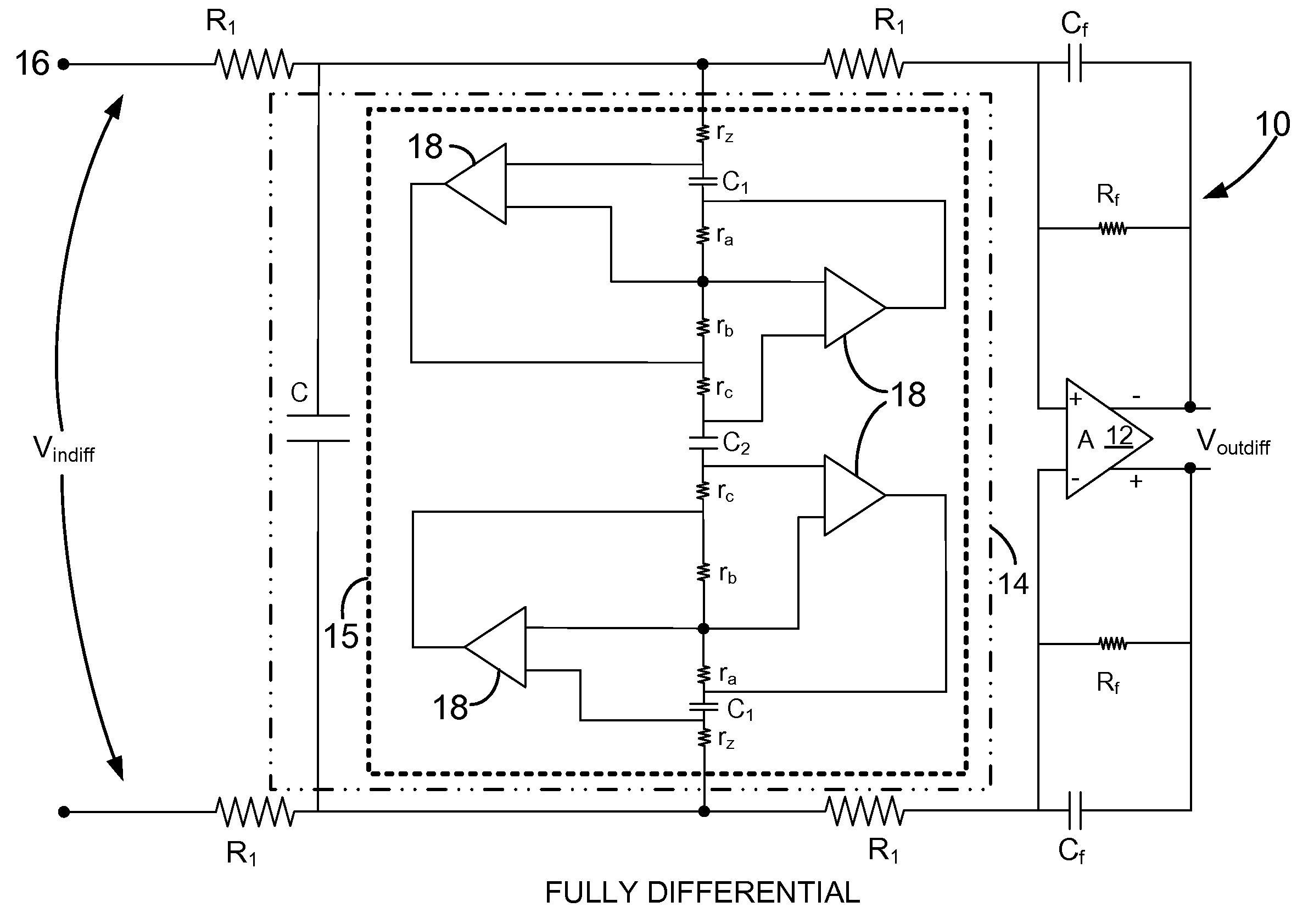
[0027]As mentioned, there remains a need for a new gain filtering and noise shaping technique capable of minimizing the requisite chip area and power consumption levels. The embodiments herein achieve this by providing a new technique to realize amplifiers with inherent noise shaped filters. Mo...


PUM


Abstract

A noise shaping and voltage gain filtering third order electrical circuit and method comprises at least one pair of input resistors; a Frequency Dependent Negative Resistance (FDNR) filter positioned in between the at least one pair of input resistors; a feedback resistor; and an amplifier operatively connected to the feedback resistor and the at least one pair of input resistors, wherein as an electrical signal is introduced to the electrical circuit, the FDNR filter is adapted to filter signal blockers out of the electrical signal prior to the electrical signal reaching the amplifier for signal amplification, wherein the FDNR filter does not contribute noise to a signal-to-noise ratio (SNR) of the electrical signal, and wherein a transfer function of the FDNR filter is substantially elliptical in shape.

Description

BACKGROUND[0001]1. Technical Field[0002]The embodiments herein generally relate to electrical filtering technologies, and, more particularly, to electrical gain filtering and noise shaping technologies.[0003]2. Description of the Related Art[0004]Active filters are often realized using transconductance-C (gm-c) topologies or op-amp based resistor / capacitance (RC) topologies. There are many ways to implement higher order filters using these two techniques. However both techniques tend to suffer from a limited noise performance. This is because the active and passive components employed in both techniques are in the signal path. Thus, they directly add noise to the signal at all frequencies (no noise shaping is employed). Hence, to achieve an acceptable post down-conversion mixer low noise filter topology using those techniques leads to an unacceptable power and chip area penalties.[0005]Furthermore, for best dynamic range performance gain and filtering should be interleaved. Moreover...

Claims


Application Information

Patent Timeline
Patent Type & Authority Patents(United States)
IPC IPC(8): H03K5/00
CPCH03H11/10H03H11/52H03H11/1291H03H11/525
Inventor ELWAN, HASSANFAHIM, AMRYOUSSOUNAN, EDWARDEMIRA, AHMED A.WANG, DEJUN
Owner ATMEL CORP
Why Eureka
Try Eureka