
Fully differential class AB amplifier and amplifying method using single-ended, two-stage amplifier

a fully differential, amplifier technology, applied in the direction of differential amplifiers, amplifiers with semiconductor devices/discharge tubes, dc-amplifiers with dc-coupled stages, etc., can solve the problem of difficult to embody a two-stage amplifier with a high gain, many restricting conditions, and large scale integration devices, etc. problems, to achieve the effect of low voltage, low power operation and high gain

Inactive Publication Date: 2009-09-08
SAMSUNG ELECTRONICS CO LTD
View PDF11 Cites 25 Cited by
  • Summary
  • Abstract
  • Description
  • Claims
  • Application Information

AI Technical Summary

Benefits of technology

[0009]To solve the above and / or other problems, exemplary embodiments of the present invention provide an amplifier that can provide a high gain, enables a low voltage and low power operation, has a simple frequency compensation and common mode feedback (CMFB) circuit, has a high slew rate, and can be embodied in a small area using a two-stage amplifier.

Problems solved by technology

As the scale down of CMOS technology continues and the demand for portable electronic products driven by batteries increases, many restricting conditions are generated in the design of very large scale integration (VLSI) devices.
In general, it is difficult to embody a two-stage amplifier with a high gain, for example, a gain over 80 dB.
Although the folded cascade amplifier is able to provide a high gain, however, it is not appropriate for an application having a low operation voltage due to a voltage headroom.
Also, the folded cascade amplifier has a complicated bias circuit so that a circuit area increases.
Since the high-gain amplifier is embodied as a multi-stage device, an increase in the circuit area is unavoidable so that a frequency compensation is difficult.
Accordingly, due to the necessity for the frequency compensation using a technology such as a nested miller compensation (NMC) or a multi-path NMC (MNMC), problems such as difficult design and power consumption according to the stage increase are present.

Method used


Image

  • Fully differential class AB amplifier and amplifying method using single-ended, two-stage amplifier
  • Fully differential class AB amplifier and amplifying method using single-ended, two-stage amplifier
  • Fully differential class AB amplifier and amplifying method using single-ended, two-stage amplifier

Examples


Embodiment Construction

[0031]Exemplary embodiments of the present invention now will be described more fully hereinafter with reference to the accompanying drawings, in which exemplary embodiments of the present invention are shown. The present invention may, however, be embodied in many different forms and should not be construed as limited to the exemplary embodiments set forth herein. Rather, these exemplary embodiments are provided so that this disclosure will be thorough and complete, and will fully convey the scope of the invention to those of ordinary skill in the art. In the drawings, like numbers refer to like elements throughout.

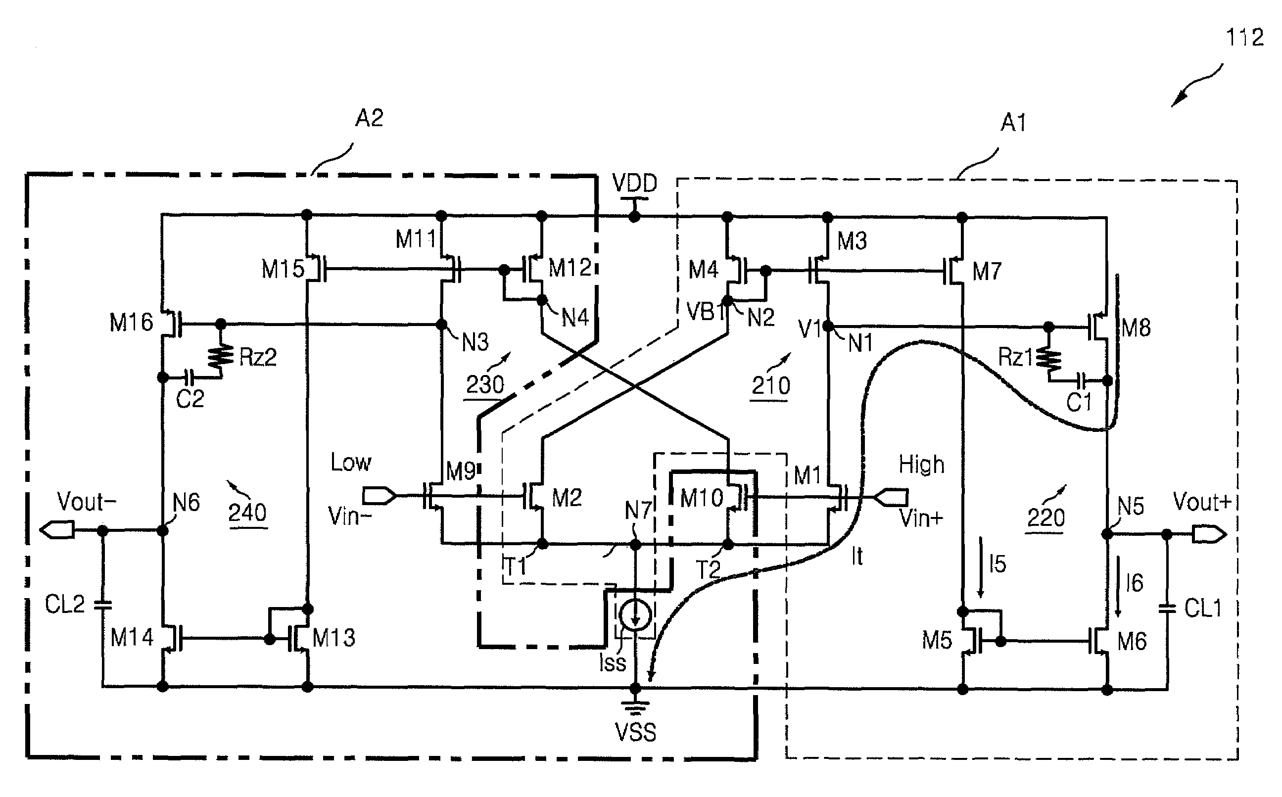
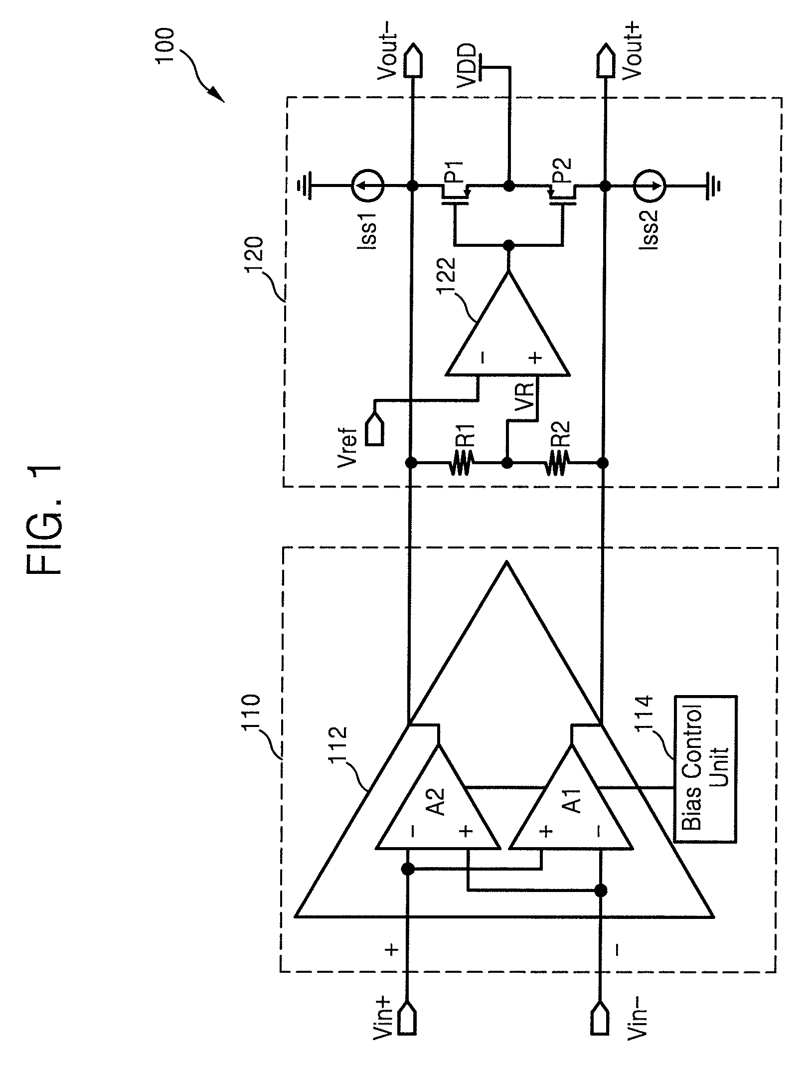
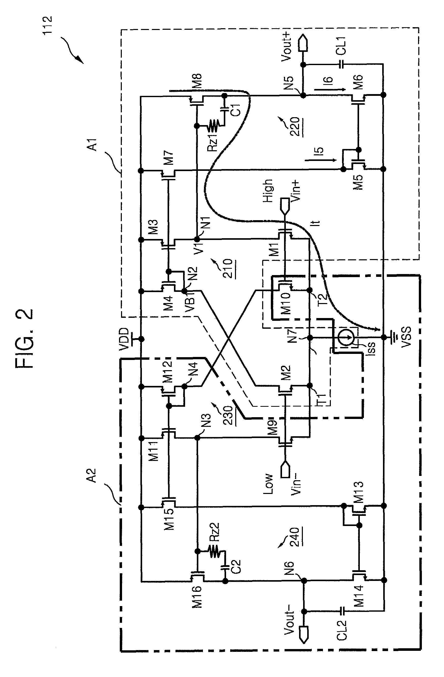
[0032]FIG. 1 is a block diagram of a fully differential class AB amplifier according to an exemplary embodiment of the present invention. Referring to FIG. 1, the fully differential class AB amplifier 100 includes a fully differential class AB amplification block 110, and a common mode feedback (CMFB) block 120.

[0033]The fully differential class AB amplification block 11...


PUM


Abstract

A fully differential amplifier includes a first single-ended current mirror type fully differential amplifier outputting a first output signal by two stage amplifying a difference between a first input signal and a second input signal and a second single-ended current mirror type fully differential amplifier outputting a second output signal by two stage amplifying a difference between the first input signal and the second input signal. A first tail of the first single-ended current mirror type fully differential amplifier and a second tail of the second single-ended current mirror type fully differential amplifier are connected to each other and the first output signal and the second output signal are differential signals.

Description

CROSS-REFERENCE TO RELATED PATENT APPLICATION[0001]This application claims priority under 35 U.S.C. § 119 from Korean Patent Application No. 2007-0029106, filed on Mar. 26, 2007, the disclosure of which is hereby incorporated by reference in its entirety.TECHNICAL FIELD[0002]The present disclosure relates to a differential amplifier and, more particularly, to a two-stage fully differential operational transconductance amplifier (OTA).DISCUSSION OF THE BACKGROUND[0003]As the scale down of CMOS technology continues and the demand for portable electronic products driven by batteries increases, many restricting conditions are generated in the design of very large scale integration (VLSI) devices. Typical restricting conditions are demands for low-voltage operation and low power consumption.[0004]As the trend to use of a system on chip (SOC) device is accelerating, not only digital circuits but also analog circuits are integrated in a single chip. Thus, the analog circuits that are typic...

Claims


Application Information

Patent Timeline
IPC IPC(8): H03F3/45
CPCH03F3/3022H03F3/45183H03F3/45475H03F2203/45364H03F2203/45134H03F2203/45318H03F3/30H03F3/45
Inventor KIM, HYOUNG RAE
Owner SAMSUNG ELECTRONICS CO LTD
Learn More