
Side emitting LED

a technology of light-emitting diodes and leds, which is applied in the direction of semiconductor devices, instruments, electrical apparatus, etc., can solve the problem of too large volume of the entire structure to apply to small-scale modules, and achieve the effect of enhancing the efficiency of luminosity

Active Publication Date: 2009-09-01
PROLIGHT OPTO TECH
View PDF3 Cites 18 Cited by
  • Summary
  • Abstract
  • Description
  • Claims
  • Application Information

AI Technical Summary

Benefits of technology

"The present invention provides a side emitting light emitting diode with a small volume that can be used in small-scale modules. The diode includes a light reflector that is mounted in the package, reducing the occupied area and improving the efficiency of the diode. The light reflector corresponds to the LED chip, reducing the light scattering distance and improving the side emitting effect. The diode has a high conductivity and reflectivity, and the light transmitting package includes a shell and a packaging gel to reflect the light and pass it through. The diode has a reduced occupied area and improved efficiency in the same area."

Problems solved by technology

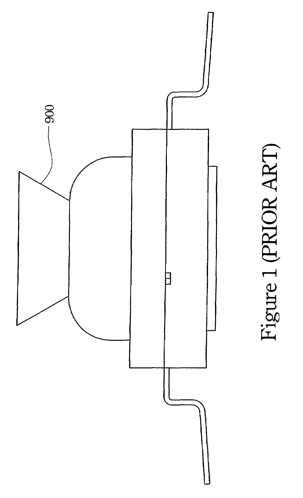
Although this kind of light emitting diode can meet the requirements for side emitting light emitting diodes, the volume of the entire structure is too large to apply to small-scale modules.

Method used


Image

  • Side emitting LED
  • Side emitting LED
  • Side emitting LED

Examples


Embodiment Construction

[0023]Reference will now be made in detail to the present preferred embodiments of the invention, examples of which are illustrated in the accompanying drawings. Wherever possible, the same reference numbers are used in the drawings and the description to refer to the same or like parts.

[0024]While the specification concludes with claims defining the features of the invention that are regarded as novel, it is believed that the invention will be better understood from a consideration of the following description in conjunction with the figures, in which like reference numerals are carried forward.

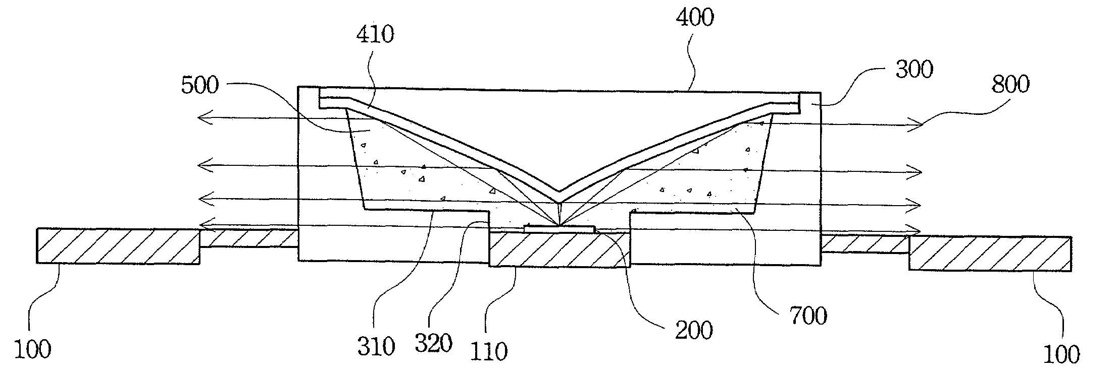
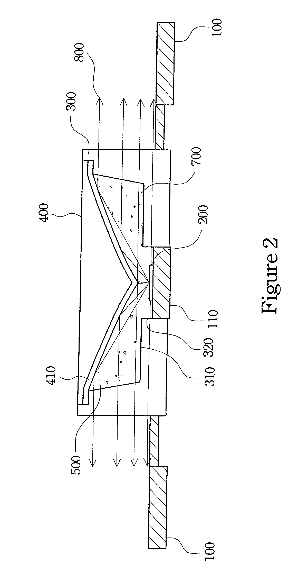
[0025]Refer to FIG. 2. FIG. 2 illustrates a schematic view of the side emitting diode of the first embodiment. The side emitting diode includes a substrate 100, a LED chip 200, a shell 300, a light reflector 400 and a packaging gel 500. The shell 300 combines with the packaging gel 500 to form a light transmitting package holding the LED chip 200.

[0026]The substrate 100 is a lead frame and i...


PUM


Abstract

A side emitting LED is provided, and it includes a substrate, at least one LED chip, a light transmitting package and a light reflector. The substrate includes a base, and the LED chip is mounted on the base. The light transmitting package is a half-closed form and is mounted on the substrate to hold the LED chip. The light reflector is disposed on the package and corresponds to the LED chip to alter the light direction radiated from the LED chip. Therefore, the light radiated from the LED chip is reflected by the corresponding light reflector and passes through the light transmitting package to be emitted laterally.

Description

RELATED APPLICATIONS[0001]This application claims priority to Taiwan Application Serial Number 95145058, filed Dec. 4, 2006, which is herein incorporated by reference.BACKGROUND[0002]1. Field of Invention[0003]The present invention relates to a light emitting diode, and more particularly to a side emitting light emitting diode with a light reflector for lateral emission.[0004]2. Description of Related Art[0005]Light emitting diodes have high reaction speeds, smaller volumes, lower power consumption, less heat radiation and extended lifetime such that conventional radiant or halogen lamps have gradually been replaced by light emitting diodes. In addition, the light emitting diode with a simple circuit design can be modulated in a small-scale and flat packaged. Thus, the light emitting diode back light module has substituted the conventional electro luminescence (EL) and cold cathode florescent lamp (CCFL) in the technology field. The light emitting diode application, like the indicat...

Claims


Application Information

Patent Timeline
Patent Type & Authority Patents(United States)
IPC IPC(8): H01L33/00H01L33/48H01L33/54H01L33/60
CPCH01L33/60G02B19/0071G02B19/0028G02B19/0061H01L33/483H01L33/54H01L2924/0002H01L2924/00
Inventor HSING CHEN, CHEN-LUNHUNG, JUNG-HAO
Owner PROLIGHT OPTO TECH
Learn More