Near field nulling antenna systems

a null and near field technology, applied in the field of near field null antenna systems, can solve the problems of degrading the performance of the receive subsystem in one or more ways, self-jamming in full duplex communication systems (i.e., systems which simultaneously transmit and receive), and reducing the coupling effect of the receive subsystem, preventing or alleviating self-jamming and/or interference suppression, and improving isolation

Active Publication Date: 2009-08-25
LOCKHEED MARTIN CORP
View PDF4 Cites 5 Cited by
  • Summary
  • Abstract
  • Description
  • Claims
  • Application Information

AI Technical Summary

Benefits of technology

[0009]According to one aspect, the present invention provides improved isolation between transmit and receive phased arrays by utilizing a technique to prevent or alleviate self jamming and / or interference suppression for transmit and receive antennas and antenna arrays in close proximity. The transmit and receive antennas and antenna arrays may operate in or close to the same frequency band. A near field nulling technique reduces the coupling between two antennas and / or antenna arrays in close proximity.
[0012]According to another embodiment of the present invention, a method for reducing self jamming in a multiple antenna system comprises the step of providing a first antenna with a first operating frequency. The first antenna has a near field with a first near region and a second near region. The first antenna has a first gain in the first near region which is lower than a second gain in the second near region. The first gain and the second gain are both at a same one of the first operating frequency and a second operating frequency. The method further comprises the step of providing a second antenna with the second operating frequency in the first near region of the near field of the first antenna.

Problems solved by technology

A major challenge in the design of full duplex communications systems (i.e., systems which simultaneously transmit and receive) is self jamming.
One kind of self jamming occurs when transmit power leaks within the transmit frequency band into the receive path.
If the leakage signal power level is sufficiently high, it may degrade the performance of the receive subsystem in one or more ways.
For example, it may drive the receive path components into compression and thus reduce sensitivity.
Moreover, depending on the receive down-conversion frequency plan, the transmit power or a spur formed in the receive chain may end up in one of the intermediate frequency (IF) bands, directly adding noise and thus reducing receive sensitivity.
Another kind of self jamming involves the leakage of spurious power generated by the transmitter which falls inside the receive band.
If this power couples into the receive path, it adds directly to the noise in the receive path, thereby degrading receive sensitivity.
Techniques utilized to offset these degradations (e.g., higher transmit power, higher antenna gain) increase satellite mass and cost.
Moreover, these filters tend to be both heavy and expensive.
This isolation requirement is a system design driver and also drives system cost and mass.
In satellite systems providing separate transmit and receive antenna systems, it increases cost and mass (which in turn increases launch cost) because two antennas must be procured and accommodated on the satellite.
Designing a satellite to place two antennas far apart (to increase spatial isolation) also increases satellite mass and cost.
The combination of this spacing constraint with the large number of radiating elements and associated electronics paths in a phased array limits the isolation level available from practical filters.

Method used


Image

  • Near field nulling antenna systems
  • Near field nulling antenna systems
  • Near field nulling antenna systems

Examples


Embodiment Construction

[0026]In the following detailed description, numerous specific details are set forth to provide a full understanding of the present invention. It will be apparent, however, to one ordinarily skilled in the art that the present invention may be practiced without some of these specific details. In other instances, well-known structures and techniques have not been shown in detail to avoid unnecessarily obscuring the present invention.

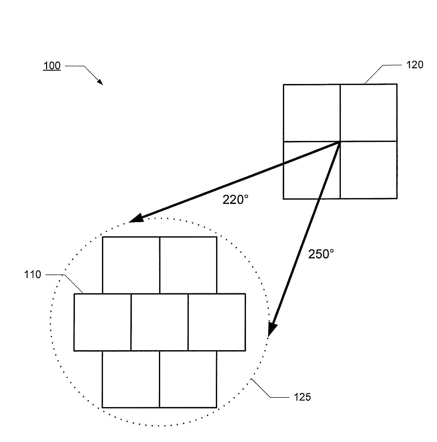
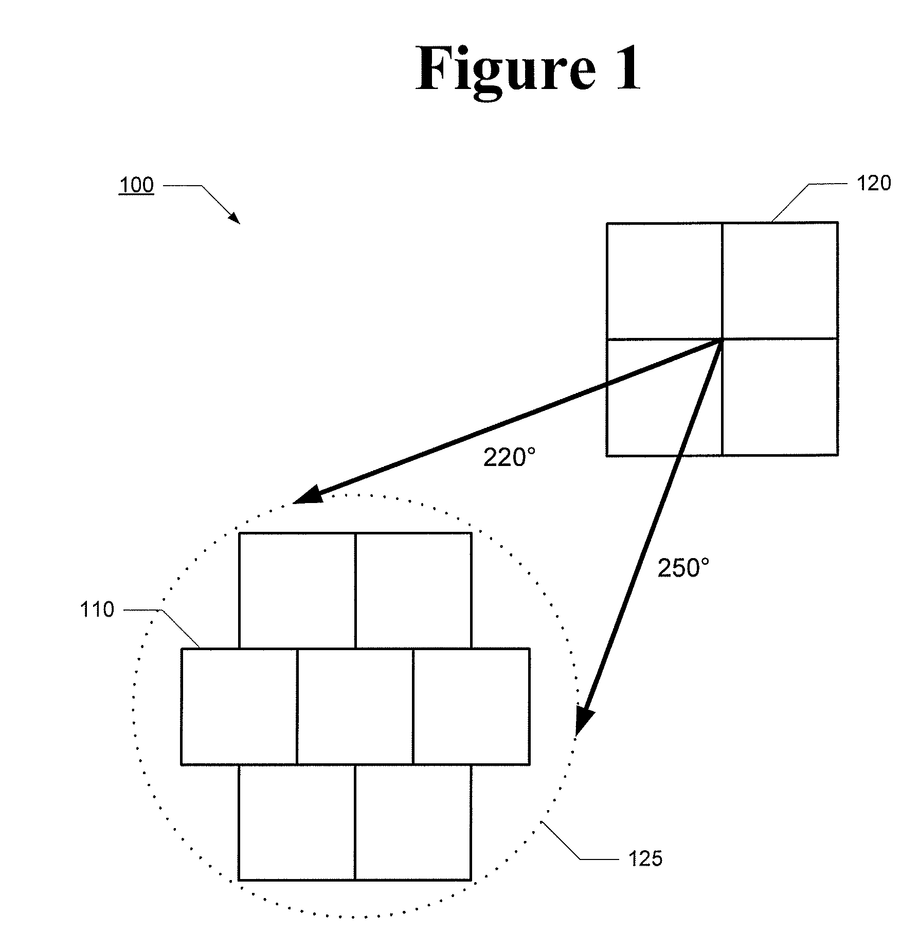
[0027]In most phased array communications systems, the phase / amplitude states of the phase / amplitude control circuits are selected to form a beam which provides high gain in the direction towards a desired point or region at some distance from the antenna. The process of selecting and applying the phase / amplitude states of the phase / amplitude control circuits to form a desired beam shape is sometimes referred to as beamforming.

[0028]In some applications it may also be necessary to provide low antenna gain towards selected points or regions which are also ...


PUM


Abstract

An antenna system is provided. The antenna system comprises a first antenna with a first operating frequency and a second antenna with a second operating frequency. The second antenna has a first near field with a first near region in which the first antenna is disposed and a second near region. The second antenna has a first gain in the first near region which is lower than a second gain in the second near region. The first gain and the second gain are both at a same one of the first operating frequency and the second operating frequency.

Description

CROSS-REFERENCE TO RELATED APPLICATION[0001]Not applicable.STATEMENT REGARDING FEDERALLY SPONSORED RESEARCH OR DEVELOPMENT[0002]Not applicable.FIELD OF THE INVENTION[0003]The present invention generally relates to antenna systems and, in particular, relates to antenna systems utilizing near field nulling.BACKGROUND OF THE INVENTION[0004]A major challenge in the design of full duplex communications systems (i.e., systems which simultaneously transmit and receive) is self jamming. One kind of self jamming occurs when transmit power leaks within the transmit frequency band into the receive path. If the leakage signal power level is sufficiently high, it may degrade the performance of the receive subsystem in one or more ways. For example, it may drive the receive path components into compression and thus reduce sensitivity. Moreover, depending on the receive down-conversion frequency plan, the transmit power or a spur formed in the receive chain may end up in one of the intermediate fr...

Claims


Application Information

Patent Timeline
IPC IPC(8): H01Q11/12
CPCH01Q3/2611
Inventor THEUNISSEN, WILHELMUS H.JACOMB-HOOD, ANTHONY W.
Owner LOCKHEED MARTIN CORP
Why Eureka
Try Eureka