Conformable skin element system for active vortex control

a technology of skin elements and vortex control, applied in the direction of airflow influencers, weapons, transportation and packaging, etc., can solve the problems of affecting the flight of the controlled aircraft, and occupying too much space to be practical, so as to improve the vehicle guidance and control

Inactive Publication Date: 2009-08-25
OCEANIT LAB
View PDF10 Cites 8 Cited by
  • Summary
  • Abstract
  • Description
  • Claims
  • Application Information

AI Technical Summary

Benefits of technology

[0009]A network of small skin elements arrayed around the forebody tip will be able to create the skin imperfections necessary to change the vortex flow while maintaining a smooth, continuous surface when active vortex control is not necessary (i.e., at low angles of attack). The elements on the windward half of the forebody surface have greater effect on the flow, and thus there should be a greater concentration of elements on the windward side, near the tip of the forebody.
[0013]Conformable skin elements may be made from piezoelectric elements or otherwise-actuated material. The conformable elements deform with the application of voltage or other external stimuli, introducing disturbances into the flow and affecting vortex formation. The system can be used to effect vortex symmetry on an aerodynamic forebody at high angle of attack. Alternatively, the devices can induce vortex asymmetry, resulting in controllable side forces that enhance vehicle guidance and control. The same elements may be used as pressure transducers, allowing for a closed-loop sensing and control system.

Problems solved by technology

Above some critical angle, the vortices may become asymmetric, leading to unpredictable side forces that can exceed the aerodynamic vehicle's control capability, resulting in a departure from controlled flight.
One of the biggest challenges that arise is that the volume near the tip of a slender forebody is limited, and active vortex control systems that employ conventional mechanical or pneumatic action to deploy the system can take too much space to be of practical use.

Method used


Image

  • Conformable skin element system for active vortex control
  • Conformable skin element system for active vortex control
  • Conformable skin element system for active vortex control

Examples


Embodiment Construction

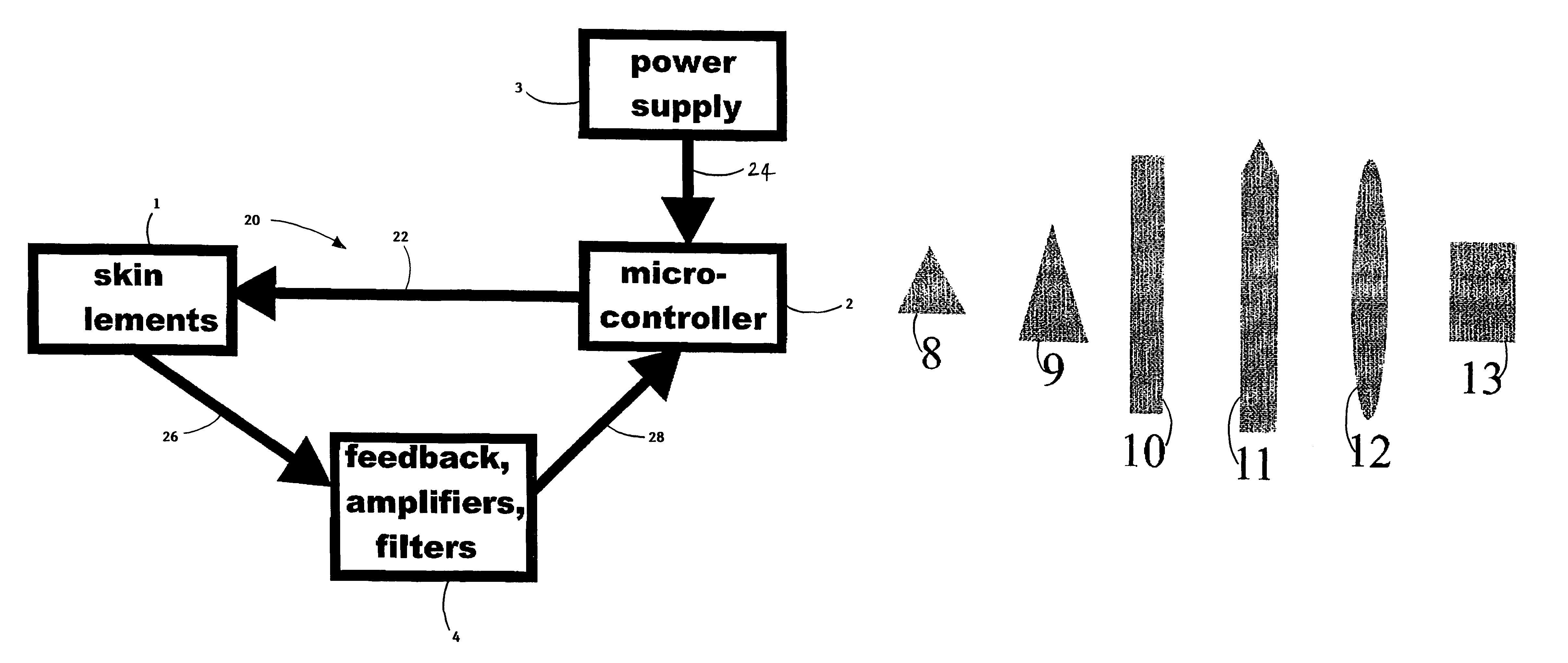
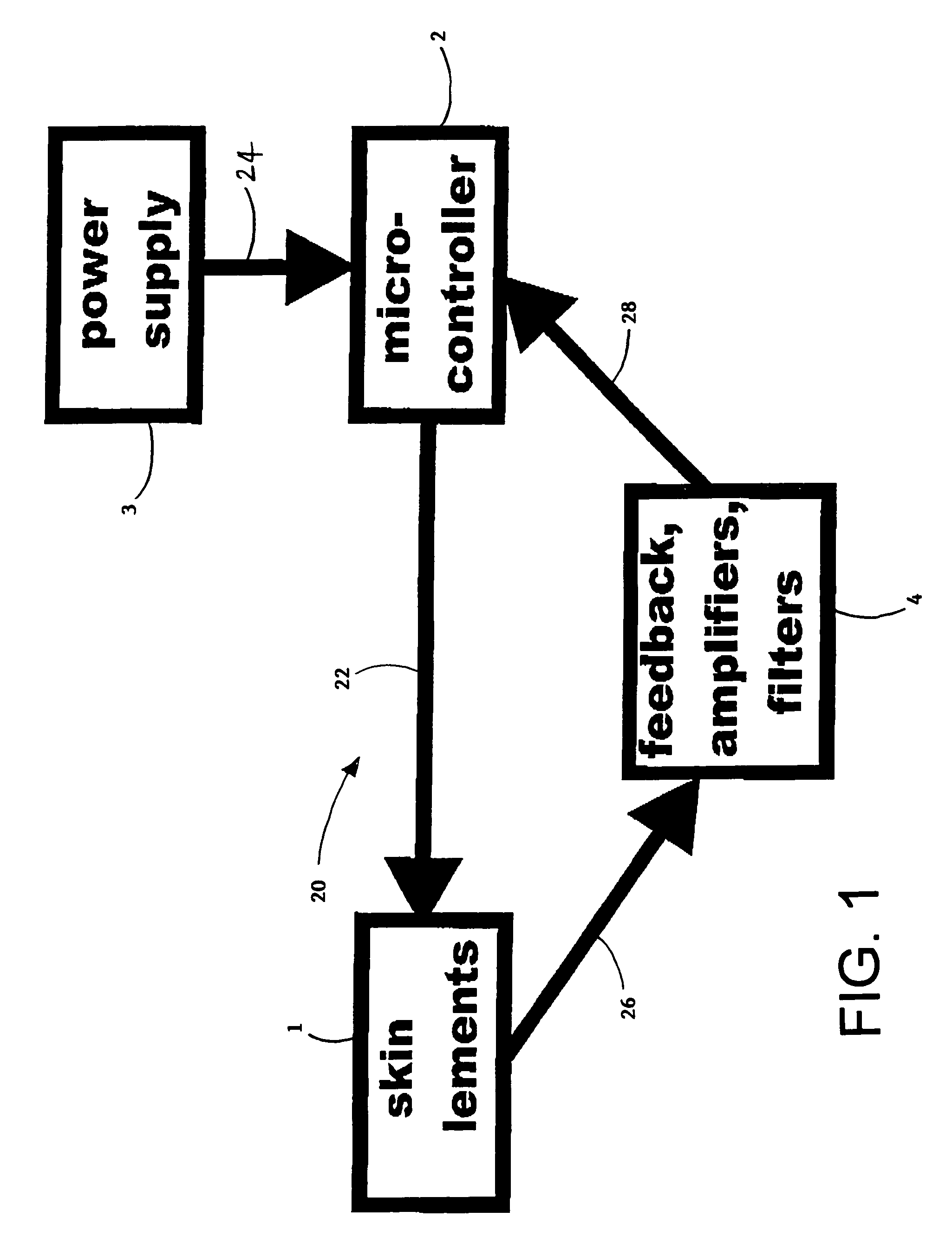
[0020]As seen in FIG. 1, a schematic diagram of conformable skin element system 20 with a feedback control loop consists of conformable skin elements 1. The skin elements 1 all have connections 22, preferably electric connections, to a micro-controller 2. Micro-controller 2 may be, for example, a computer chip that determines which skin elements to activate depending on sensed signals from feedback 4. Power supply 3 is provided 24 to the micro-controller 2 from any known power supply such as, but not limited to, battery or vehicle power.

[0021]The skin elements act as pressure-transducers and provide pressure-transducer signals 26 to the feedback loop 4. Feedback loop 4, which comprises amplifiers and filter, takes the pressure-transducer signals 26 and amplifies and filters the signals and transmits 28 to micro-controller 2.

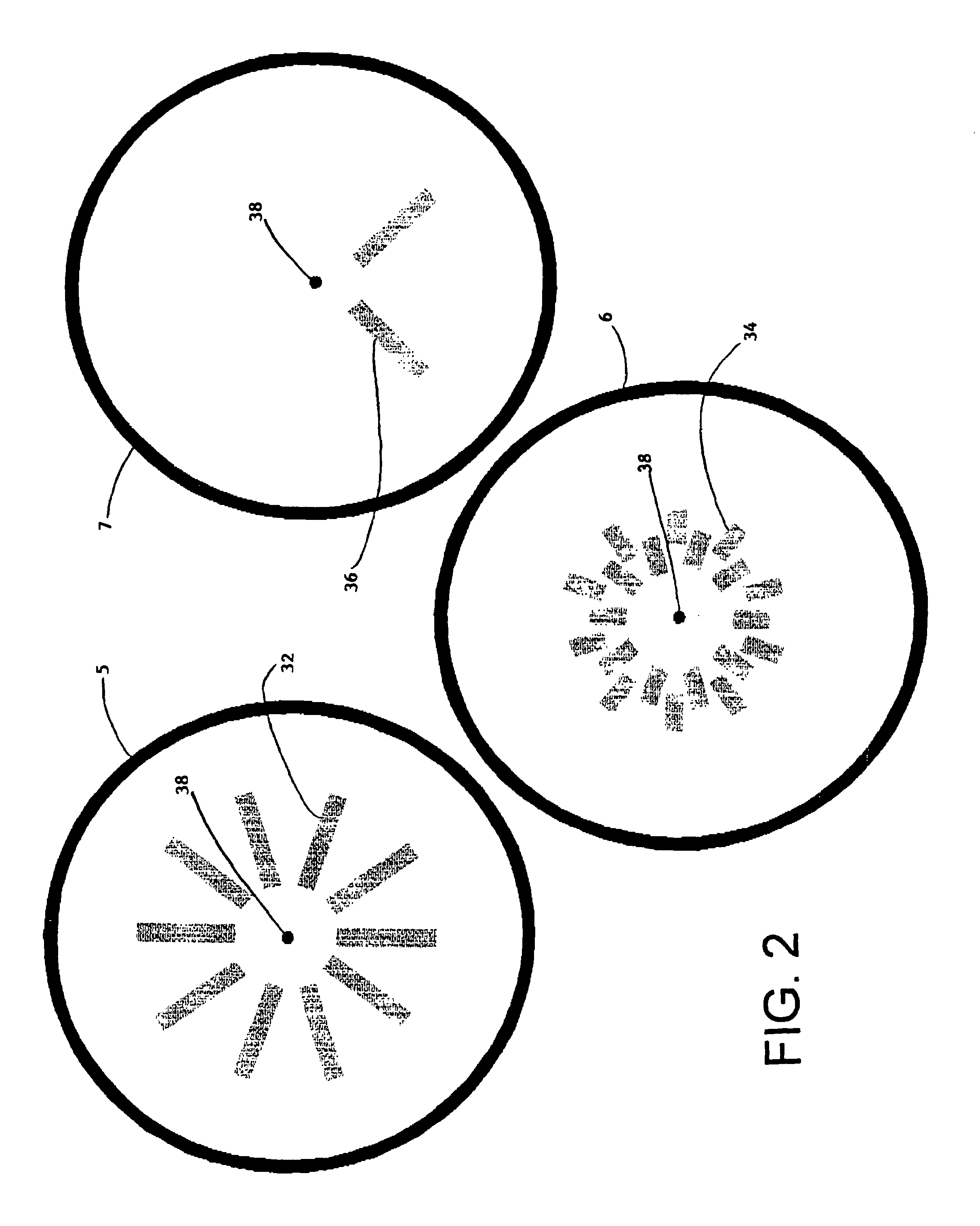
[0022]FIG. 2 shows different configurations 32, 34, 36, exemplary of the skin elements. Forebody 5, 6, 7, viewed from a front vantage point has tip 38 generally ...


PUM


Abstract

Conformable skin elements provide active vortex control. The skin element is mounted on a surface and acts like a pressure transducer and flow modifier. A micro-processor is coupled to the skin element and a feedback loop for controlling activation of the skin-element corresponding to surface pressures detected on the skin element. Additional pressure transducers may be provided for communicating with the feedback loop. These may include surface mounted taps or manometers and the like. Wires connect the skin elements, the feedback loop, and the micro-processor for conducting voltage to the skin elements and for transmitting pressure signals from the skin element via the feedback loop to the micro-processor. The skin element may be mounted on the surface by any known mounting system. Perimeter mounts on the skin element allow bulge deflection while cantilevered mounts allow cantilever deflection of the skin element. Aerodynamic forebody surfaces have the skin elements mounted circumferentially about a tip of the forebody. There may be one or more skin elements mounted according to the desired function. The skin elements may be of any shape.

Description

[0001]This application claims the benefit of U.S. Provisional Application No. 60 / 239,252, filed Oct. 12, 2000.BACKGROUND OF THE INVENTION[0002]Flow past a slender body of revolution at high angle of attack separates from the leeward side of the body and rolls up into a pair of vortices. The aerodynamic forces imparted by the vortices enhance the lift of the vehicle. Above some critical angle, the vortices may become asymmetric, leading to unpredictable side forces that can exceed the aerodynamic vehicle's control capability, resulting in a departure from controlled flight.[0003]Studies have shown that vortex asymmetry at high angles of attack is triggered by minute imperfections, or micro-asymmetries, located at the nose tip of the slender body. Numerous techniques have been used to actively control forebody vortex asymmetry, including suction / blowing (Yuan, Staudacher), strakes (Murri, Walters, Staudacher, Rao), and inflatable membranes (Zell), to varying degrees of success.[0004]T...

Claims


Application Information

Patent Timeline
IPC IPC(8): B64C13/16
CPCB64C23/005F42B10/62B64C2230/12Y02T50/166Y02T50/10
Inventor CHEUNG, KEN C. K.SULLIVAN, CHRISTOPHER J.
Owner OCEANIT LAB
Why Eureka
Try Eureka