
Method and device for evaluation of jointing regions on workpieces

a technology of jointing region and workpiece, which is applied in the direction of electric/magnetic/electromagnetic heating, instruments, television systems, etc., can solve the problems of inability to obtain a high-quality weld seam, the joint is not detected, and the edge damage of the parts is not visible, so as to improve the recording of grey-level images, improve the inspection of the joint, and add separation

Active Publication Date: 2009-08-18
PRECITEC VISION +1
View PDF57 Cites 98 Cited by
  • Summary
  • Abstract
  • Description
  • Claims
  • Application Information

AI Technical Summary

Benefits of technology

"The invention provides an improved method for detecting joints by evaluating a grey-level image to assess the quality of the joint. This method can detect not just the position of the joint but also measure the gap width and detect edge damage. The use of a CMOS sensor arrangement with a non-linear characteristic, particularly a logarithmic characteristic, improves the recording of the grey-level image and the light pattern of the light section method. The invention also provides an apparatus for detecting a joint between workpieces with a light line projection unit and a recording unit for recording the light line and a grey-level image, and an image evaluation unit for the light line and the grey-level image. The recording unit has a non-linear characteristic for the light line and a linear characteristic for the grey-level image. This allows for the detection of the position of the joint before it is made, controlling the welding beam."

Problems solved by technology

When materials are joined together, particularly by welding though also by adhesive bonding, the problem of detecting the joint arises.
It is also necessary that edge damage to the parts should be detected, as it is not possible to obtain a high-quality weld seam between edges that are damaged.

Method used


Image

  • Method and device for evaluation of jointing regions on workpieces
  • Method and device for evaluation of jointing regions on workpieces
  • Method and device for evaluation of jointing regions on workpieces

Examples


Embodiment Construction

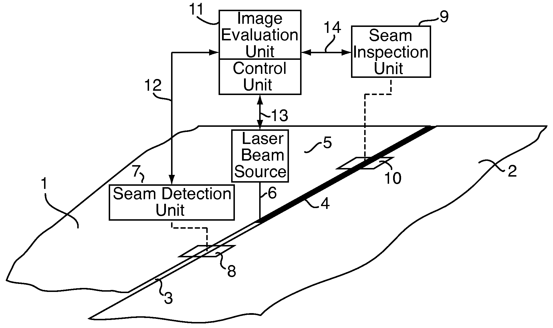
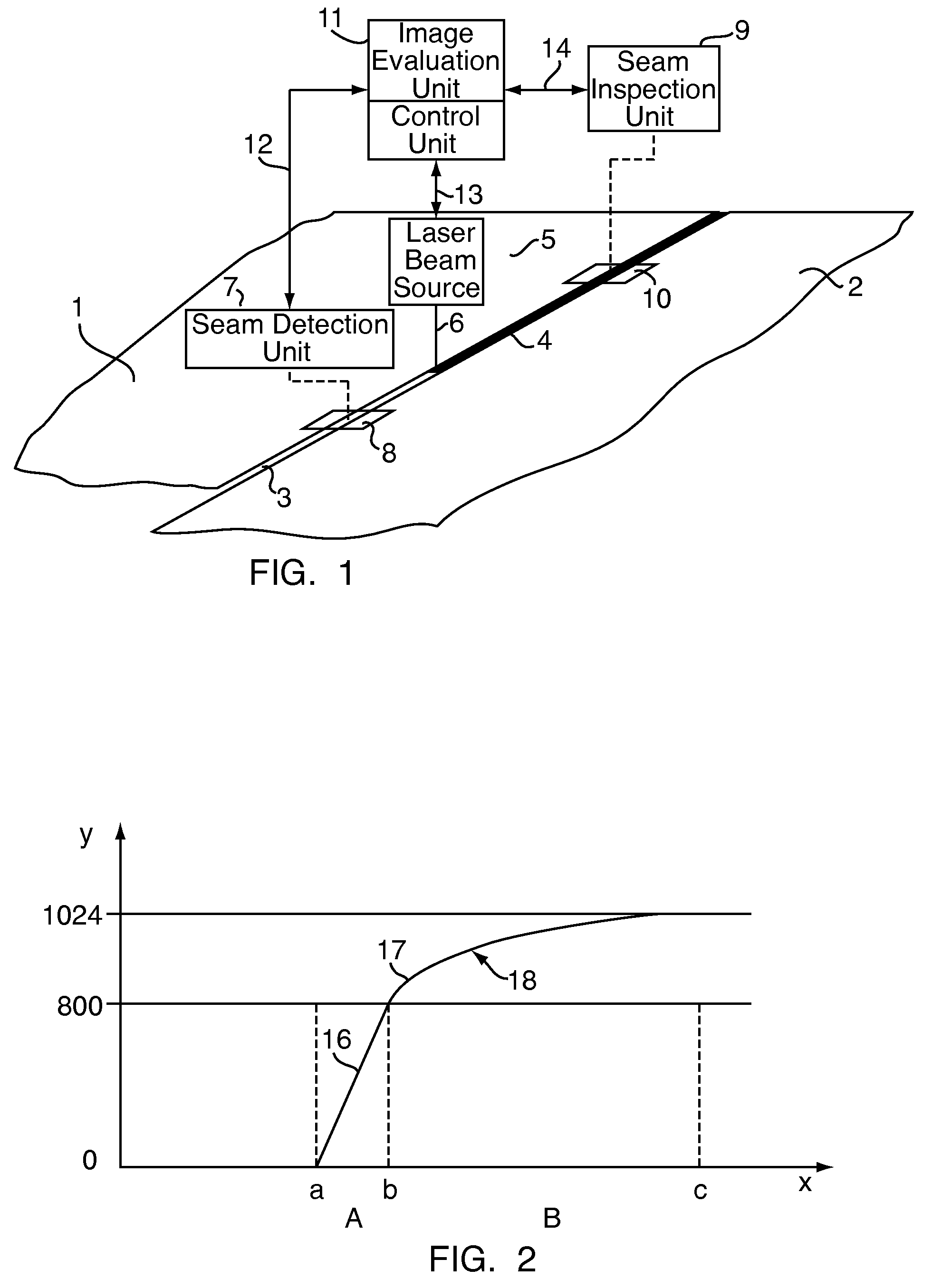
[0025]FIG. 1 shows schematically the welding of a tailored blank (Platine) which is made up of metal sheets 1 and 2 butted together along a joint line 3. Sheet-metal components (usually flat) of different thickness and / or different material properties are joined to make a single element, the tailored blank (Platine). Usually this element is subsequently shaped into a component, e.g., a component for a motor vehicle. A laser beam 6 from a laser beam source 5 is guided along the joint line 3, welding the sheets 1 and 2 together and leaving the weld seam 4 behind it. It is immaterial whether the laser beam source 5 moves over stationary workpieces or the workpieces are traversed past a stationary laser. It is known to ascertain the position of the joint line 3 with a seam detection unit 7 in order that the laser beam source 5 and beam 6 can be made to follow the course of the joint line exactly. In a known manner, the course of the joint line 3 is detected by the light section method a...


PUM

PropertyMeasurementUnit
scanning frequencyaaaaaaaaaa
wavelengthaaaaaaaaaa

Abstract

A method and apparatus for detecting a joint between workpieces is provided. At least one light line is recorded by the light section method to detect the three-dimensional course of the joint and a grey-level image of the joint is also recorded. The grey-level image is evaluated to assess the quality of the joint.

Description

[0001]Applicants hereby claim foreign priority benefits under 35 U.S.C. §119 of Swiss Patent Application No. 2101 / 01 filed Nov. 15, 2001 and PCT Application No. PCT / CH02 / 00613 filed Nov. 14, 2002, the disclosures of which are herein incorporated by reference.BACKGROUND OF THE INVENTION[0002]1. Technical Field[0003]The invention relates to methods for detecting joints between workpieces, and also to an apparatus for detecting a joint between workpieces. The invention further relates to apparatus and methods for seam tracking.[0004]2. Background Information[0005]When materials are joined together, particularly by welding though also by adhesive bonding, the problem of detecting the joint arises. This is true in the case of both spot joints (spot welds, spot bonds) and linear joints (weld seam, adhesive bead). Detection may take place both before and after the joining process, and is here understood as meaning on the one hand ascertainment of the position, and on the other hand ascerta...

Claims


Application Information

Patent Timeline
Patent Type & Authority Patents(United States)
IPC IPC(8): G06K9/00B23K9/28H04N9/47G01B11/24B23K9/095B23K9/127B23K26/03B23K31/00G01B11/30
CPCB23K9/0956B23K9/1274G01B11/303B23K26/045B23K26/032B23K2201/185B23K26/044B23K2101/185B23K9/127
Inventor SCHWARZ, JOACHIMHALSCHKA, MARTIN
Owner PRECITEC VISION
Learn More