Over driver control signal generator in semiconductor memory device

a technology of overdriver and signal generator, which is applied in the direction of pulse manipulation, pulse technique, instruments, etc., can solve the problems of excessive voltage level, sudden increase of voltage vcore in its voltage level, and difficulty in amplifying data in a great deal of cells, etc., and achieve stable voltage level

Active Publication Date: 2009-08-11
SK HYNIX INC
View PDF16 Cites 2 Cited by
  • Summary
  • Abstract
  • Description
  • Claims
  • Application Information

AI Technical Summary

Benefits of technology

[0028]It is, therefore, an object of the present invention to provide an over-driver control signal generating unit in a semiconductor memory device, capable of procuring a stable voltage level in a normal driving voltage stage without respect to a voltage level of a power supply voltage.

Problems solved by technology

It is, however, difficult to amplify data in a great deal of cells by using the core voltage VCORE for short time in a trend in lowering an operational voltage.
However, under high power voltage condition where the power supply voltage VDD is about 2V, the transistor M1 of the BLSA supply line driving unit 60 supplies an excessive current to the core voltage VCORE during an over-driving interval, such that the core voltage VCORE suddenly increases in its voltage level to thereby have an excessive voltage level.
In case where a voltage level of the core voltage VCORE excessively rises as described above, there occurs a problem that an operational characteristic degrades to incur a poor device.
However, an effect thereof is insignificant.

Method used


Image

  • Over driver control signal generator in semiconductor memory device
  • Over driver control signal generator in semiconductor memory device
  • Over driver control signal generator in semiconductor memory device

Examples


Embodiment Construction

[0045]Hereinafter, an over-driving pulse generating circuit in accordance with exemplary embodiments of the present invention will be described in detail with reference to the accompanying drawings.

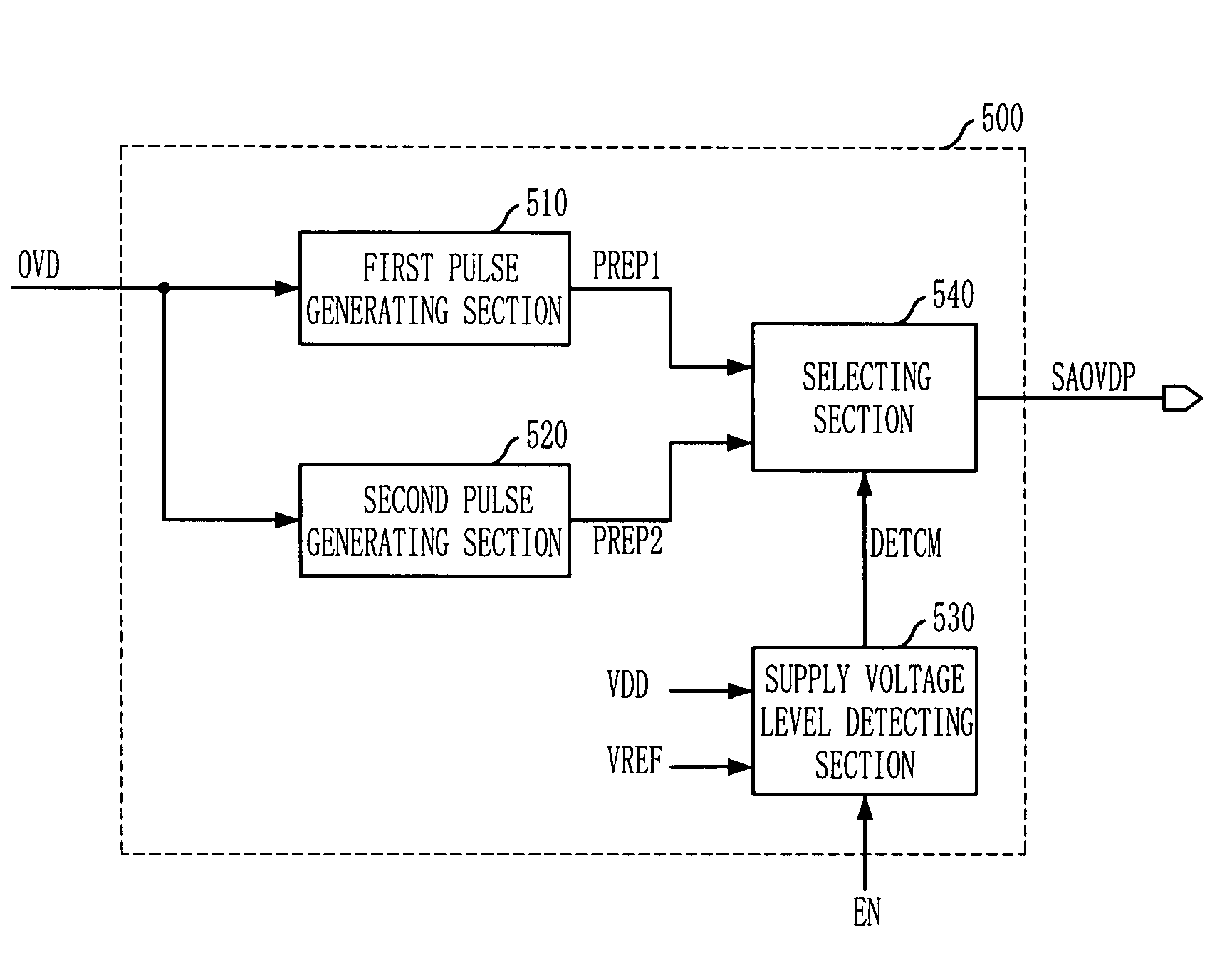
[0046]FIG. 6 shows a block diagram of an over-driving pulse generating unit 500 in a semiconductor memory device in accordance with a first preferred embodiment of the present invention.

[0047]The over-driving pulse generating unit 500 in accordance with the first preferred embodiment of the present invention includes a first pulse generating section 510, a second pulse generating section 520, a supply voltage level detecting section 530, and a selecting section 540.

[0048]The first pulse generating section 510 generates a first pulse signal PREP1 having a first pulse width in response to an over-driving signal OVD generated by an active command ACT. The second pulse generating section 520 generates a second pulse signal PREP2 having a second pulse width shorter than the first pulse width i...


PUM


Abstract

An over-driver control signal generating apparatus includes a pulse generating unit for generating a pulse signal having a pulse width corresponding to a desired over-driving interval in response to an over-driving signal; a supply voltage level detecting unit for detecting a voltage level of a supply voltage to generate a detecting signal; and a selecting unit for outputting the pulse signal as a bit line over-driver control signal in response to the detecting signal.

Description

CROSS-REFERENCES TO RELATED APPLICATIONS[0001]The present invention claims priority of Korean patent application numbers 10-2006-96955 and 10-2006-96957, filed on Oct. 2, 2006, which are incorporated by references in their entirety.BACKGROUND OF THE INVENTION[0002]The present invention relates to a bit line over-driving scheme in a semiconductor memory device, and more particularly, an over-driving pulse generating circuit for controlling an over-driver.[0003]As a continuous scale-down with respect to a line width and size of cells constituting a semiconductor memory chip has progressed, a voltage lowering of a power supply voltage has accelerated, and accordingly, there has been a demand for a design technique for satisfying a performance required under low power voltage condition.[0004]Now, most semiconductor memory chips are equipped with an internal voltage generator for generating an inner voltage to supply itself with a voltage required for operating an internal circuit in a c...

Claims


Application Information

Patent Timeline
Patent Type & Authority Patents(United States)
IPC IPC(8): G11C8/00
CPCG11C5/143G11C5/145G11C7/12G11C11/4094H03K5/04G11C11/4074H03K2005/00293
Inventor KANG, KHIL-OHK
Owner SK HYNIX INC
Why Eureka
Try Eureka