Electric storage battery construction and method of manufacture

a technology of electric storage batteries and manufacturing methods, applied in the direction of sustainable manufacturing/processing, cell components, wound/folded electrode electrodes, etc., can solve the problems of very demanding requirements for batteries for implantable medical devices, and achieve the effects of minimizing battery size, enhancing battery reliability, and efficient battery manufacturing

Inactive Publication Date: 2009-08-04
QUALLION
View PDF169 Cites 11 Cited by
  • Summary
  • Abstract
  • Description
  • Claims
  • Application Information

AI Technical Summary

Benefits of technology

[0006]The present invention is directed to an electric storage battery incorporating one or more aspects described herein for enhancing battery reliability while minimizing battery size. In addition, the invention is directed to a method for efficiently manufacturing the battery at a relatively low cost.
[0009]In accordance with a further significant aspect of the invention, the outer layer of the jellyroll is particularly configured to minimize the size, i.e., outer radius dimension, of the jellyroll. More particularly, in the exemplary preferred embodiment, the active material is removed from both faces of the negative electrode substrate adjacent its outer end. The thickness of each active material coat can be about 0.04 mm and the thickness of the negative substrate can be about 0.005 mm. By baring the outer end of the negative electrode substrate, it can be adhered directly, e.g., by an appropriate adhesive tape, to the next inner layer to close the jellyroll to while minimizing the roll outer radius dimension.

Problems solved by technology

Batteries for implantable medical devices are subject to very demanding requirements, including long useful life, high power output, low self-discharge rates, compact size, high reliability over a long time period, compatibility with the patient's internal body chemistry, etc.

Method used


Image

  • Electric storage battery construction and method of manufacture
  • Electric storage battery construction and method of manufacture
  • Electric storage battery construction and method of manufacture

Examples


Embodiment Construction

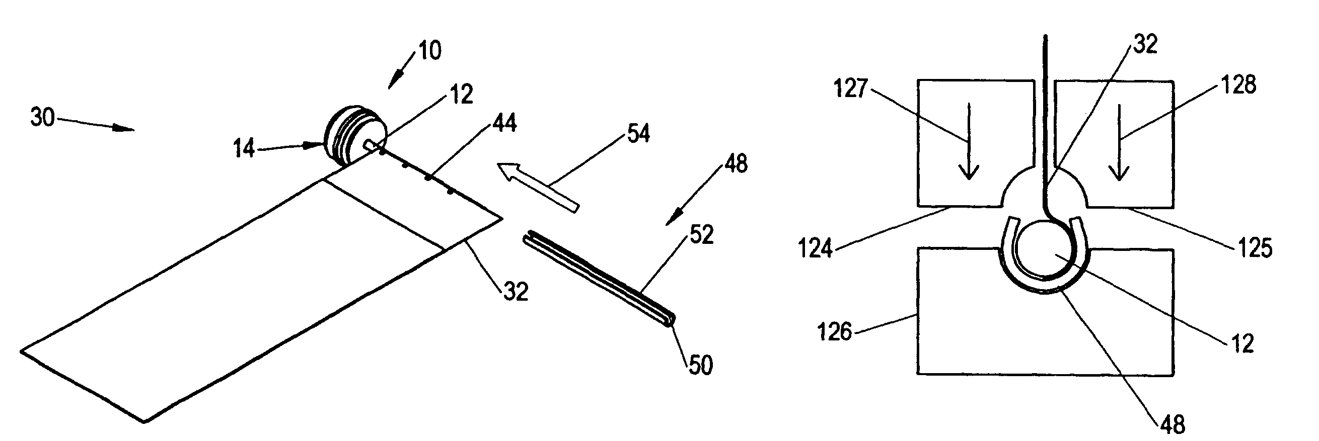
[0036]Attention is initially directed to FIGS. 1 and 2 which illustrate a preferred feedthrough pin subassembly 10 utilized in accordance with the present invention. The subassembly 10 is comprised of an elongate pin 12, preferably formed of a solid electrically conductive material, having low electrical resistance and high corrosion resistance such as platinum iridium, preferably 90Pt / 10Ir. The pin 12 extends through, and is hermetically sealed to a header 14. The header 14 is comprised of dielectric disks, e.g., ceramic, 16 and 18 which sandwich a glass hollow cylinder 20 therebetween. The glass hollow cylinder is hermetically sealed to the pin 12. The outer surface of the glass hollow cylinder 20 is sealed to the inner surface of an electrically conductive hollow member 22, e.g., titanium-6Al-4V. As will be seen hereinafter, the conductive hollow material 22 functions as a battery case endcap in the final product to be described hereinafter.

[0037]Attention is now directed to FIGS...


PUM

PropertyMeasurementUnit
diameteraaaaaaaaaa
lengthaaaaaaaaaa
lengthaaaaaaaaaa

Abstract

An electric storage battery and method of manufacture thereof characterized by a feedthrough pin which is internally directly physically and electrically connected to an inner end of a positive electrode substrate. A C-shaped mandrel extends around the pin and substrate end enabling the pin / mandrel to be used during the manufacturing process as an arbor to facilitate winding layers of a spiral jellyroll electrode assembly. The pin additionally extends from the battery case and in the final product constitutes one of the battery terminals with the battery case comprising the other terminal. Active material is removed from both sides of the outer end of the negative electrode in the jellyroll to allow room for adhesive tape to secure the jellyroll. The electrolyte is injected through the open end of the case after the endcap is welded to the negative electrode but before sealing the endcap to the case. The electrolyte is preferably injected through the C-shaped mandrel to facilitate and speed filling.

Description

CROSS-REFERENCE TO RELATED APPLICATIONS[0001]This application is a Divisional of U.S. patent application Ser. No. 10 / 167,688, filed Jun. 12, 2002 now U.S. Pat. No. 6,670,071, which claims the benefit of U.S. Provisional Application No. 60 / 348,665, filed Jan. 15, 2002, each of which is incorporated herein by reference in its entirety.FIELD OF THE INVENTION[0002]This invention relates generally to electric storage batteries and more particularly to a battery construction, and method of manufacture thereof, suitable for use in implantable medical devices.BACKGROUND OF THE INVENTION[0003]Rechargeable electric storage batteries are commercially available in a wide range of sizes for use in a variety of applications. As battery technology continues to improve, batteries find new applications which impose increasingly stringent specifications relating to physical size and performance. Thus, new technologies have yielded smaller and lighter weight batteries having longer storage lives and h...

Claims


Application Information

Patent Timeline
Patent Type & Authority Patents(United States)
IPC IPC(8): H01M2/08H01M6/10H01M10/04H01M50/119H01M50/541H01M50/548H01M50/559
CPCH01M2/027H01M2/0275H01M2/0421H01M2/263H01M6/10H01M10/0431H01M2/30H01M2/022Y10T29/49112Y10T29/4911Y10T29/49108Y10T29/49115Y02E60/10H01M50/107H01M50/545H01M50/154Y02P70/50H01M50/559H01M50/548H01M50/119
Inventor SKINLO, DAVID M.TSUKAMOTO, HISASHISZYSZKOWSKI, ANDREWPARKHOUSE, LEONZOLOTNIK, VLADIMIR
Owner QUALLION
Why Eureka
Try Eureka