Semiconductor device with improved arrangement of a through-hole in a wiring substrate
a technology of semiconductor devices and wiring substrates, which is applied in the direction of semiconductor devices, semiconductor/solid-state device details, electrical apparatus, etc., can solve the problems of poor wiring layout efficiency, inability to make small wiring substrates, and extremely narrow space between respective bump lands, so as to shorten the wiring route from the through hole to an external terminal , the effect of miniaturizing the semiconductor devi
- Summary
- Abstract
- Description
- Claims
- Application Information
AI Technical Summary
Benefits of technology
Problems solved by technology
Method used
Image
Examples
embodiment 1
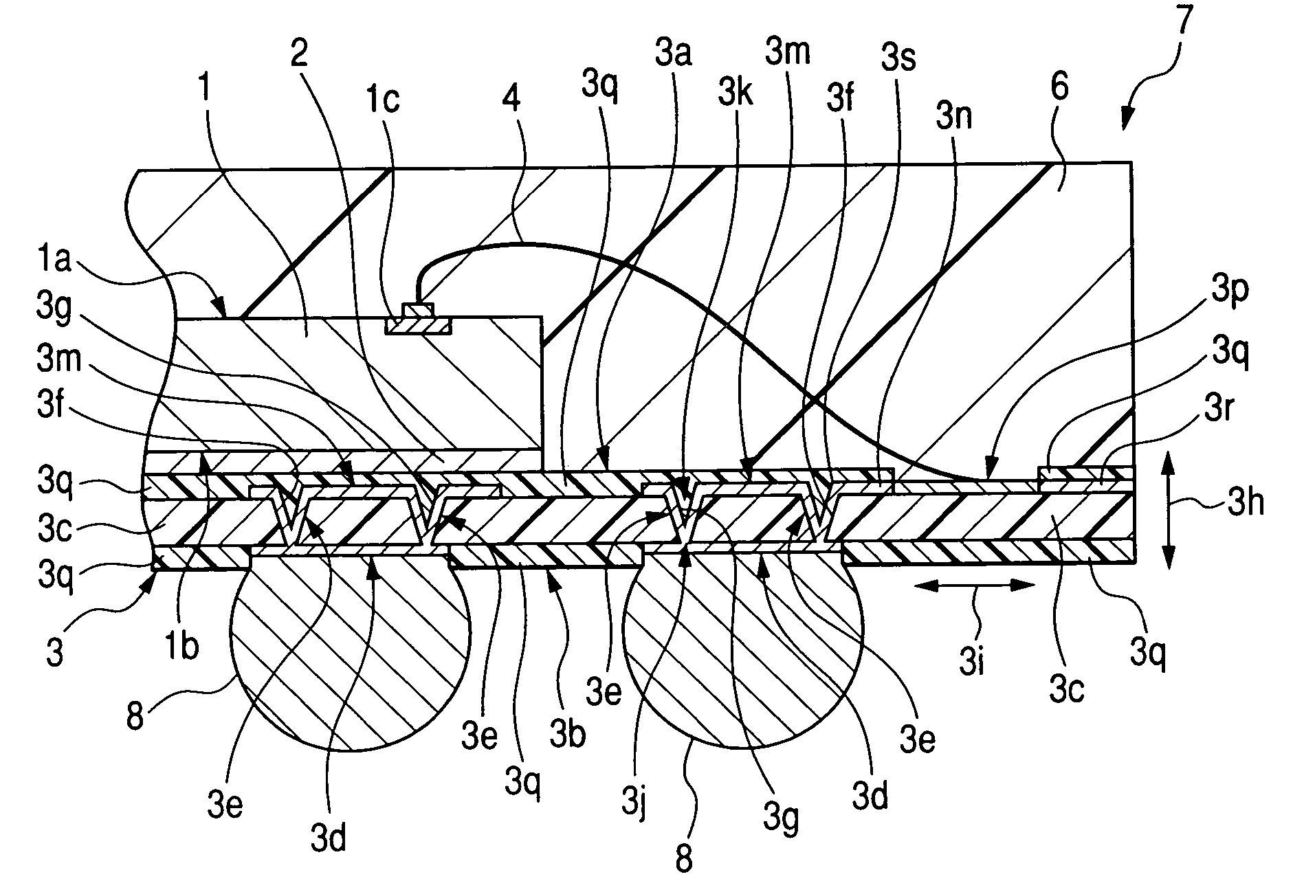
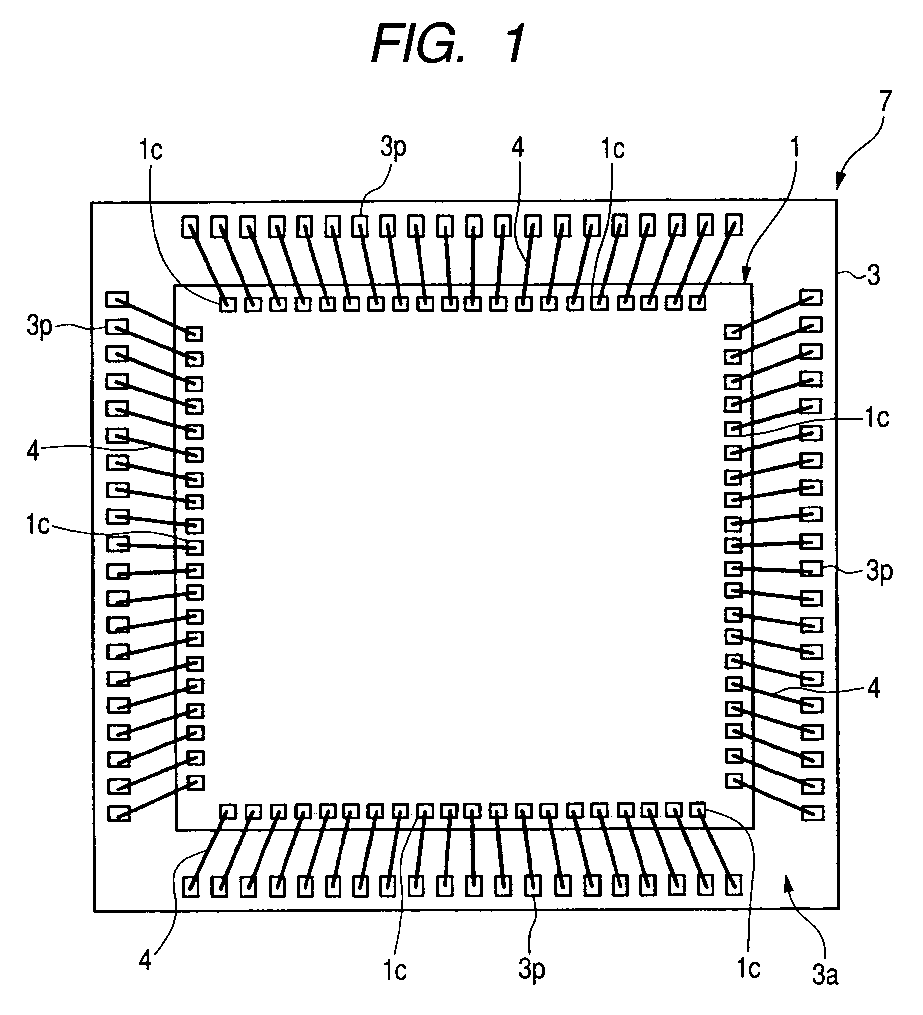
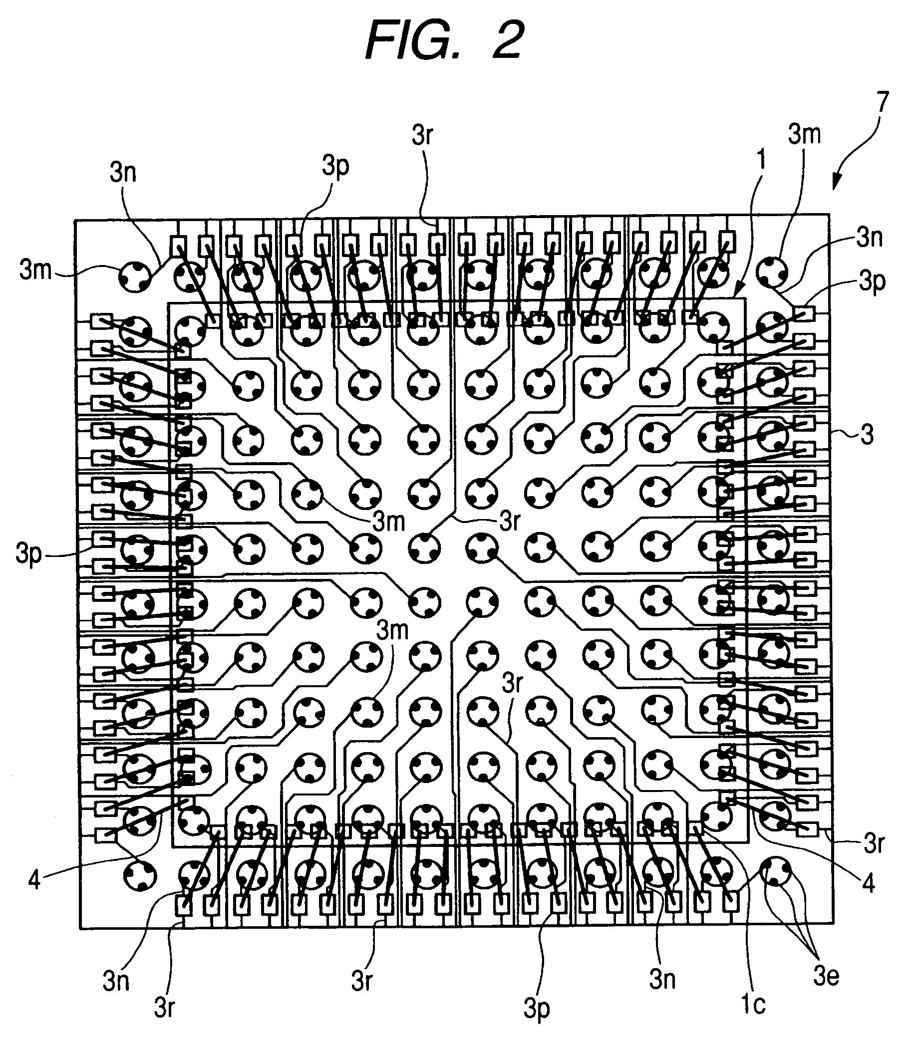
[0063]FIG. 1 is a plan view showing an example of the structure of the semiconductor device of Embodiment 1 of the present invention, FIG. 2 is a plan view showing an example of the conductor pattern on the main surface side of a wiring substrate penetrating a molded body and a semiconductor chip in the semiconductor device shown in FIG. 1, FIG. 3 is a sectional view showing an example of the structure of the semiconductor device shown in FIG. 1, FIG. 4 is an enlarged partial sectional view showing the structure of the section A shown in FIG. 3; FIG. 5 is a plan view showing an example of the structure of the wiring substrate included in the semiconductor device shown in FIG. 1; FIG. 6 is a sectional view showing an example of the structure of the wiring substrate shown in FIG. 5, FIG. 7 is an enlarged partial sectional view showing the structure of the section A shown in FIG. 6, FIG. 8 is a manufacturing process flow chart showing an example of the assembly up to a resin molding in...
embodiment 2
[0112]FIG. 21 is a plan view showing an example of the conductor pattern on the main surface side of a wiring substrate penetrating a molded body and a semiconductor chip in the semiconductor device of Embodiment 2 of the present invention; FIG. 22 is a sectional view showing an example of the structure of the semiconductor device shown in FIG. 21, FIG. 23 is an enlarged partial sectional view showing the structure of the section A shown in FIG. 22, FIG. 24 is a plan view showing an example of the structure of the wiring substrate included in the semiconductor device shown in FIG. 21, FIG. 25 is a sectional view showing an example of the structure of the wiring substrate shown in FIG. 24, FIG. 26 is an enlarged partial sectional view showing the structure of the section A shown in FIG. 25, FIG. 27 is a plan view showing the conductor pattern on the main surface side of a wiring substrate penetrating a molded body and a semiconductor chip in the semiconductor device of the modificati...
embodiment 3
[0121]FIG. 30 is a plan view showing an example of the conductor pattern on the main surface side of a wiring substrate penetrating a molded body and a semiconductor chip in the semiconductor device of Embodiment 3 of the present invention, FIG. 31 is a sectional view showing an example of the structure of the semiconductor device shown in FIG. 30, FIG. 32 is an enlarged partial sectional view showing the structure of the section A shown in FIG. 31, FIG. 33 is a plan view showing an example of the structure of the wiring substrate included in the semiconductor device shown in FIG. 30, FIG. 34 is a sectional view showing an example of the structure of the wiring substrate shown in FIG. 33, FIG. 35 is an enlarged partial sectional view showing the structure of the section A shown in FIG. 34, and FIG. 36 is a plan view showing the conductor pattern on the main surface side of the wiring substrate of the modification of Embodiment 3 of the present invention.
[0122]The semiconductor devic...
PUM
 Abstract
Description
Claims
Application Information
 - Generate Ideas
- Intellectual Property
- Life Sciences
- Materials
- Tech Scout
- Unparalleled Data Quality
- Higher Quality Content
- 60% Fewer Hallucinations
Browse by: Latest US Patents, China's latest patents, Technical Efficacy Thesaurus, Application Domain, Technology Topic, Popular Technical Reports.
© 2025 PatSnap. All rights reserved.Legal|Privacy policy|Modern Slavery Act Transparency Statement|Sitemap|About US| Contact US: help@patsnap.com


