Apparatus adapted for membrane-mediated electropolishing

a technology of electropolishing apparatus and electropolishing process, which is applied in the direction of electrolysis components, manufacturing tools, lapping machines, etc., can solve the problems of incompatible mechanically fragile materials, high cost of cmp process, and inability to planarize mechanically fragile materials, etc., to achieve superior ability, reduce roughness, and the effect of reducing the roughness

Inactive Publication Date: 2009-07-28
EI DU PONT DE NEMOURS & CO
View PDF45 Cites 21 Cited by
  • Summary
  • Abstract
  • Description
  • Claims
  • Application Information

AI Technical Summary

Benefits of technology

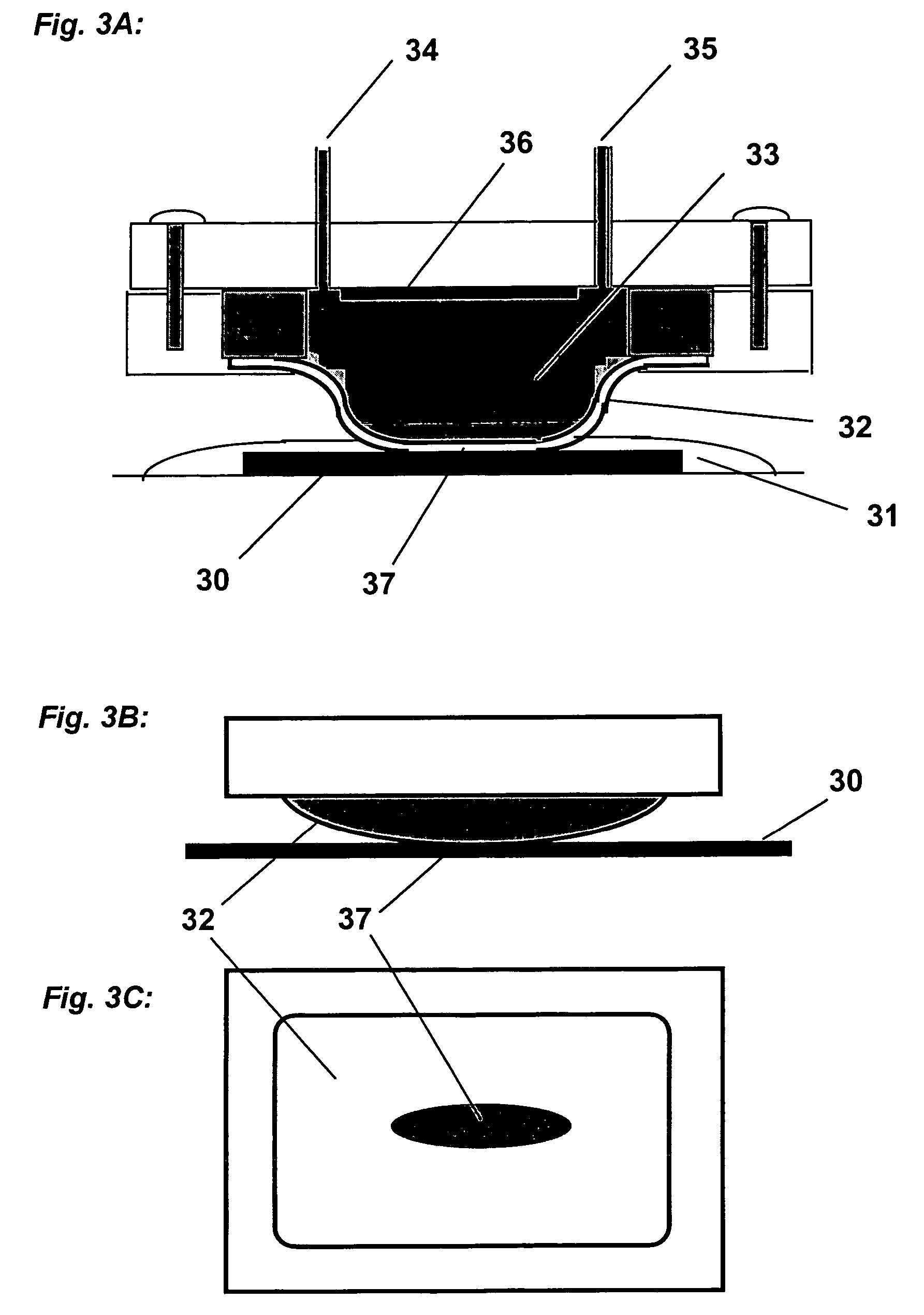
[0017]The present invention comprises a new type of EP process called membrane-mediated electropolishing (MMEP). MMEP is primarily distinguished from EP in that in MMEP the work-piece does not contact the electrolyte. Rather, the work-piece is in contact, and is preferably wetted by, a low-conductivity fluid. The MMEP apparatus has a conductive electrolyte composition, e.g., solution or gel, in contact with a cathode. A charge-selective ion-conducting membrane disposed between the electrolyte and the work-piece comprises first and second sides, wherein on the first side the membrane contacts the conductive fluid electrolyte composition and is thereby in electrical contact with the cathode, and on the second side the membrane contacts a work-piece having a thin layer low-conductivity fluid disposed thereon. A layer of low-conductivity fluid is disposed between the charge-selective ion-conducting membrane and the work-piece, though in preferred embodiments the membrane sensibly contacts the surface of the work-piece, and the layer of low-conductivity fluid is exceedingly thin. Current flow from the cathode to the work-piece passes through the half-cell fluid, the membrane, and the low-conductivity fluid. When the work-piece is substantially coated by a low-conductivity solvent such as pure water, a suitable voltage difference is applied, and the surface of the work-piece is brought into contact with the external surface of the membrane. Metal ions generated at the work-piece become solvated by the low-conductivity solvent, migrate through the membrane and electrolyte solution and are advantageously electroplated onto the cathode. The planarization efficiency of the MMEP process for features with lateral dimensionsλ≧10 microns is much greater than EP and also much greater than a theoretically ideal EP process [as described by C. Wagner, J. Electrochem. Soc., 101, 225 (1954)]. Moreover, under suitable conditions the MMEP process is capable of planarizing such features on typical Cu plated damascene wafers to final amplitudes (residual dishing) a of less than 0.02 micron. Accordingly MMEP offers unique practical advantages for planarizing typical Cu plated damascene wafers without need for specialized masking or mechanical abrasion. A substantial portion of the metallic material electropolished from the work-piece permeates through the membrane toward the cathode. In the preferred embodiments, virtually all (e.g., greater than 95%, for example greater than 98%) of the metal ions generated in MMEP are captured by the cathode half-cell, i.e., pass through the membrane and into the electrolyte composition. These metal ions, or alternatively the same or other metal ions already supplied in the electrolyte, are advantageously plated onto the cathode, so that the amount of metal salts in the electrolyte remains constant. Consequently, Membrane-Mediated Electropolishing consumes little or no chemicals and generates virtually no waste products. The work-piece in MMEP never directly contacts the electrolyte solution, and essentially all metal ions produced by anodic dissolution are transferred across the membrane and into the cell. Thus the work-piece remains free of contamination by toxic, damaging, and / or corrosive chemicals typical of electropolishing electrolytes and traditional CMP formulations, and is also free of mobile ion contamination.
[0045]The MMEP apparatus may further include a substantially sealed enclosure surrounding the work-piece and / or half-cell, wherein substantially sealed enclosure contains an inert gas at a pressure above atmospheric pressure. It is important to control the exposure of low-conductivity fluid to the atmosphere prior to use to exclude unwanted dissolved gases and unwanted particulate contamination. A clean room in a integrated circuit fabrication plant generally keeps the level of particulates and volatile solvents in the air to pre-determined acceptable levels, but do not keep levels of carbon dioxide to sufficiently low levels to not adversely affect the performance of the most preferred embodiments of this invention, e.g., where the conductivity of the low-conductivity fluid is less than about 5 μS / cm. At such low-conductivity, atmospheric carbon dioxide can readily dissolve into the low-conductivity water and can thereby substantially increase the conductivity of the low-conductivity fluid, e.g., water. This substantially sealed enclosure surrounding the work-piece and half-cell can exclude gases such as carbon dioxide which can readily dissolve into low-conductivity fluid after the low-conductivity fluid is applied to the substrate, and can exclude particulates. Additionally, the enclosure can simplify safe handling of molecular oxygen generated (by electrolysis of water) near the work-piece and molecular hydrogen generated (by electrolysis of water) near the cathode, for example by applying sufficient gas flow that these components do not form a combustible mixture, or by keeping the majority of the molecular hydrogen from contacting the majority of generated oxygen, or combination thereof.
[0046]A variation of any of the above-mentioned apparatus further includes a window-frame-like structure disposed between the charge-selective ion-conducting membrane and the work-piece, wherein said a window-frame-like structure has holes therethrough which allow the membrane to contact the work-piece, wherein the size of the holes will depend on among other requirements on the thickness of the protective membrane. Exemplary window-frame-like structures have a shape similar to a gauze, a screen, or window frames, i.e., regularly shaped frames about contact areas. Such structure can reduce wear on a membrane, increase contact area between a membrane and the work-piece, assist in the distribution of low-conductivity fluid across the area being polished, assist in removing oxygen gas generated by the electrolysis of water, assist in providing electrical contact from the power supply to the surface of the work-piece, or any combination of the above.
[0058]MMEP is useful for polishing and planarizing work-pieces of various compositions, including both pure metals and alloys. Accordingly MMEP has utility for many of the same metal finishing applications currently addressed by conventional EP. MMEP can provide several practical advantages over EP for those applications and also for other applications such as planarization of copper damascene wafers where conventional EP suffers from intrinsic limitations as previously discussed. One advantage of MMEP over EP is its superior ability to reduce roughness and to planarize a surface. As detailed above, for features of large lateral dimensions (λ>10 microns) the planarization efficiency of MMEP is intrinsically much greater than that of EP under typical conditions with convected electrolyte, and is also much greater than for an ideal EP process with no convection. Moreover, convection is essential for most applications of EP because in the absence of convection, polishing is too slow and non-uniform to be of practical value. Moreover, under certain conditions MMEP is capable of planarizing Cu damascene wafers featuring humps and dishing in the plated topography without the use of additional means such as masking, or mechanical abrasion.
[0059]At the same time, MMEP provides the advantage over EP and electromechanical polishing processes in that strong acid electrolytes and metal salts never contact the wafer work-piece. Moreover, the work-piece in MMEP never directly contacts the electrolyte solution, and essentially all metal ions produced by anodic dissolution are transferred across the membrane and into the cell. Thus the work-piece remains free of contamination by toxic and / or corrosive chemicals typical of EP electrolytes.

Problems solved by technology

However, CMP is a costly process, generates hazardous waste products, and is incompatible with the mechanically fragile materials currently under development for improved dielectric layers.

Method used


Image

  • Apparatus adapted for membrane-mediated electropolishing
  • Apparatus adapted for membrane-mediated electropolishing
  • Apparatus adapted for membrane-mediated electropolishing

Examples


example 1

Membrane-mediated Electropolishing of Cu Coupons

[0438]A cathode half-cell was constructed for membrane-mediated electropolishing (MMEP) whose cross-section is shown schematically in FIG. 3. The half-cell comprised a polypropylene base (1) bolted to a stainless steel faceplate (2) which framed an opening approximately 1.0 cm×2.5 cm. This opening was covered by a piece of Nafion® membrane (4) (NE1135, 3.5 mil thick) sealed against the faceplate by means of a silicone rubber gasket (approximately 0.5 cm thick. A piece of copper foil (6) was sealed to the base and electrically connected to a wire on the outside of the half-cell. The cavity (5) defined by base, gasket and membrane contained two ports (7) connected to Teflon® tubing (OD 1 / 16″) through which the electrolyte (0.2 M copper sulfate in 40% phosphoric acid) was continuously re-circulated by means of a peristaltic pump (not shown) from an external reservoir. Electrolyte was pumped through the half-cell at approximately 10 ml / min...

example 2

Comparison of Membrane-mediated and Conventional Electropolishing

[0442]Two copper coupons (1.5″×2.0″) were milled as in Example 1 and then masked with tape so that only an area of 0.71 cm2 was exposed. One of these coupons was polished by MMEP using the same procedure as in Example 1. The second coupon was polished by the conventional electropolishing (EP) method. For EP a silicone rubber gasket ⅜″ thick was used to separate the work-piece from a sheet of copper foil which served as the cathode. A cylindrical cavity in this gasket provided a volume between the work-piece and cathode filled by electrolyte solution that was continuously pumped through cavity. The area of work-piece exposed to electrolyte in the EP cell was the same as that polished by the MMEP process. The same electrolyte (0.2 M Copper sulfate in 40% phosphoric acid) and the same pumping rate was used in both sets of polishing experiments. The root-mean-square roughness Rg was measured by profilometry and the results...

example 3

Comparison of Membrane-mediated and Conventional Electropolishing for Planarizing Surfaces with Large-λ Features

[0445]A copper coupon was polished to a mirror finish using jeweler's rouge, then laminated to a dry-film photoresist (Riston® 9415, E.I. Dupont de Nemours and Company, Inc., Wilmington, Del.). The photoresist film was covered with a lithographic negative patterned with 100 micron lines interspersed with 100 micron spaces, and then exposed and developed under conditions recommended by the manufacturer (DuPont Riston® Printed Circuit Materials, RD 1, New James St., Towanda, Pa. USA 18848-9784). The exposed areas on the coupon were etched for 1 minute in a 5% solution of sodium monopersulfate (Sigma-Aldrich, Milwaukee, Wis.), followed by conventional electropolishing at 2.0 V and 1.5 coul / cm2 (as described in Example 2). The resist mask was then removed by soaking in dichloromethane, leaving a corrugated surface with alternating 100 micron trenches and 100 micron plateaus. T...


PUM

PropertyMeasurementUnit
conductivityaaaaaaaaaa

Abstract

This invention provides a membrane-mediated electropolishing apparatus for polishing and / or planarizing metal work-pieces. The work-piece is wetted with a low-conductivity fluid. The wetted work-piece is contacted with a first side of a charge-selective ion-conducting membrane, wherein the second side contacts a conductive electrolyte solution in electrical contact with a electrode. Current flow between the electrode and the work-piece electropolishes metal from the work-piece. This invention also provides a half-cell adapted for use in membrane-mediated electropolishing having a fully or partially enclosed volume, a conductive electrolyte which partially or essentially fills the enclosed volume, an electrode which is in contact with the electrolyte, and a charge-selective ion-conducting membrane which seals one surface of the enclosed volume, cavity or vessel in such a way that the internal surface of said membrane contacts the electrolyte solution or gel and the external surface is accessible to contact the work-piece.

Description

RELATED APPLICATIONS[0001]This application claims priority to the following pending provisional applications: Appln. No. 60 / 546,198 by Stephen MAZUR and Charles E. JACKSON filed on Feb. 23, 2004; Appln. No. 60 / 546,192 by Stephen MAZUR and Charles E. JACKSON filed on Feb. 23, 2004; Appln. No. 60 / 570,967 by Stephen MAZUR and Charles E. JACKSON filed on May 14, 2004; and Appln. No. 60 / 611,699 by Stephen MAZUR and Charles E. JACKSON filed on Sep. 22, 2004, the disclosures of which are each incorporated herein by reference thereto for all purposes.STATEMENT REGARDING FEDERALLY SPONSORED OR DEVELOPMENT[0002]N / AINCORPORATION-BY-REFERENCE OF MATERIAL SUBMITTED ON A COMPACT DISC[0003]N / ASEQUENCE LISTING[0004]N / AFIELD OF THE INVENTION[0005]This invention relates to an apparatus for polishing metal surfaces, and more specifically an apparatus adapted to perform an electropolishing process, wherein a portion of metal is removed from the surface by means of electrochemical anodic oxidation. More...

Claims


Application Information

Patent Timeline
Patent Type & Authority Patents(United States)
IPC IPC(8): C25F3/02C25F7/00B23H5/08C25F3/16H01L21/321
CPCB23H5/08B24B37/042C25F3/02H01L21/7684H01L21/32115H01L21/32125C25F7/00
Inventor MAZUR, STEPHENJACKSON, JR., CHARLES E.FOGGIN, GARY W.
Owner EI DU PONT DE NEMOURS & CO
Why Eureka
Try Eureka