
Method of manufacturing nozzle plate, nozzle plate, liquid ejection head and image forming apparatus

a technology of liquid ejection head and nozzle plate, which is applied in the direction of printing, etc., can solve the problems of complex manufacturing process, increased manufacturing cost, and deterioration of liquid philicity produced with the passage of time, and achieves the effect of simplifying the manufacturing process

Inactive Publication Date: 2009-07-21
FUJIFILM CORP
View PDF3 Cites 7 Cited by
  • Summary
  • Abstract
  • Description
  • Claims
  • Application Information

AI Technical Summary

Benefits of technology

The present invention provides a method for manufacturing a nozzle plate with a simplified manufacturing process. The method eliminates steps of removing liquid-repelling film, resist, and the like. A liquid-repelling film is formed on the nozzle plate forming substrate, followed by a liquid-philic film formation step. The liquid-philic film is then solidified. The invention also provides a nozzle plate with improved liquid ejection characteristics and control of back pressure. The method includes a step of solidifying the liquid-repelling film by irradiating radiation onto it. The invention also provides a liquid ejection head and an image forming apparatus with the improved nozzle plate.

Problems solved by technology

However, the oxygen plasma processing in Japanese Patent Application Publication No. 9-267478 does not produce sufficient liquid-philicity, and moreover, the produced liquid-philicity deteriorates with the passage of time.
Furthermore, since the interface between the base material and the liquid-repelling film makes contact with the ink, then there may be erosion at the interface and corrosion of the base material.
However, the manufacturing method requires steps for removing the liquid-repelling film and the resist, and the like, and this makes the manufacturing process more complicated.
For example, if etching is performed to remove the liquid-repelling film, then it is difficult to achieve uniform reaction speed and churning of the solvent and the etching depth of the resist, between the nozzles, and this gives rise to ejection nonuniformity between the nozzles.
Moreover, blasting and ashing, and the like, are also possible methods for removing the liquid-repelling film; however, it is difficult with these methods to uniformly remove the liquid-repelling film at all of the nozzles without damaging the base material.
Further, it is also possible to form a liquid-repelling film that is readily removable, by adjusting the composition of the liquid-repelling film; however, the liquid-repelling film of this kind would have weak resistance to scratching and the action of chemicals, thus leading to deterioration in production specifications.
Furthermore, in a method which uses mask processing with a resist, an interface between the liquid-repelling film and the liquid-philic film becomes present inside the nozzle, and the interface does not coincide with the meniscus position formed at the opening section of the nozzle, and hence it can lead to deterioration in the ink supply performance, as well as making the control of the back pressure more difficult.

Method used


Image

  • Method of manufacturing nozzle plate, nozzle plate, liquid ejection head and image forming apparatus
  • Method of manufacturing nozzle plate, nozzle plate, liquid ejection head and image forming apparatus
  • Method of manufacturing nozzle plate, nozzle plate, liquid ejection head and image forming apparatus

Examples


Embodiment Construction

General Composition of Inkjet Recording Apparatus

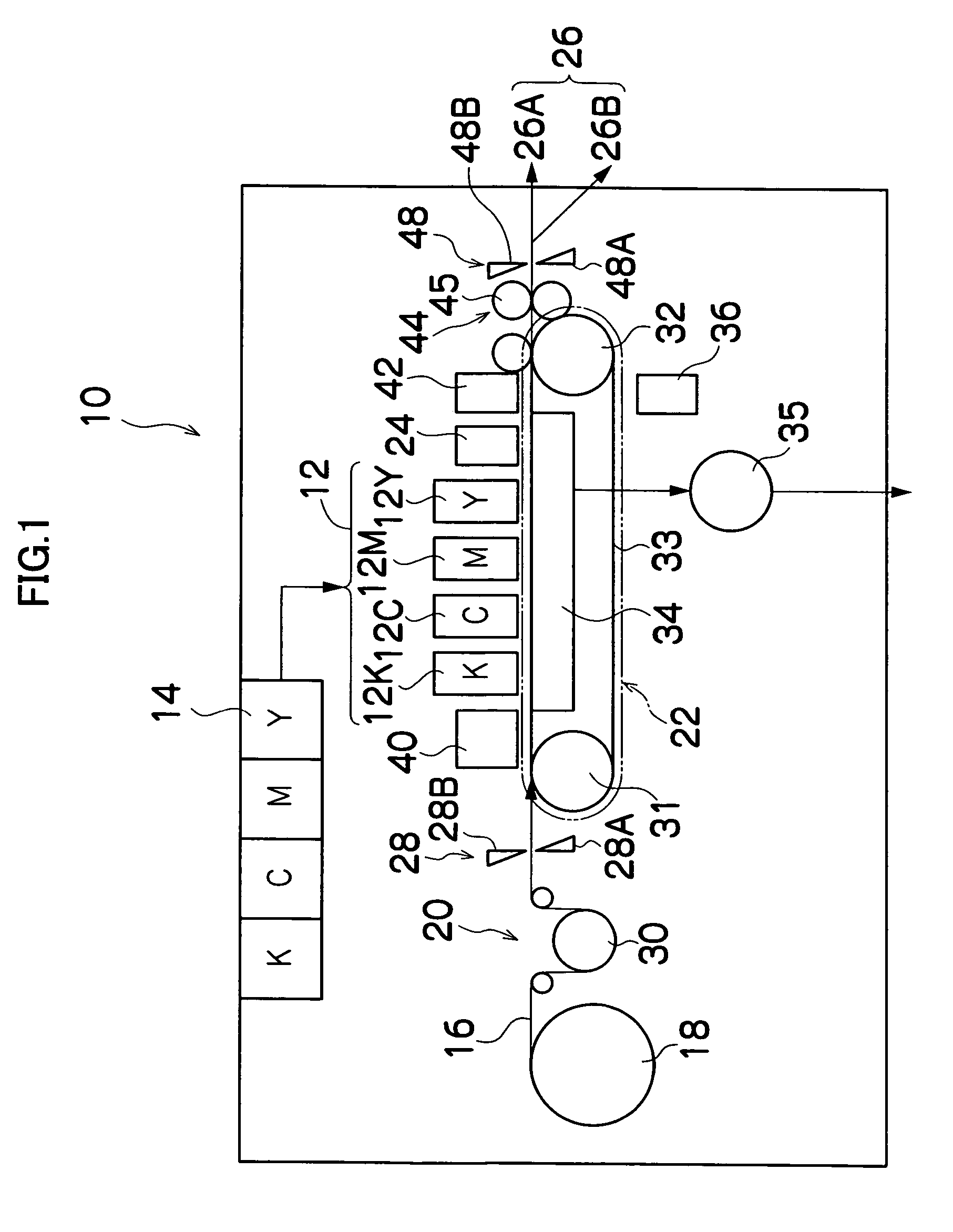
[0032]FIG. 1 is a general schematic drawing of an inkjet recording apparatus which forms an image forming apparatus according to an embodiment of the present invention. As shown in FIG. 1, the inkjet recording apparatus 10 comprises: a printing unit 12 having a plurality of print heads 12K, 12C, 12M, and 12Y for ink colors of black (K), cyan (C), magenta (M), and yellow (Y), respectively; an ink storing and loading unit 14 for storing inks of K, C, M and Y to be supplied to the print heads 12K, 12C, 12M, and 12Y; a paper supply unit 18 for supplying recording paper 16; a decurling unit 20 for removing curl in the recording paper 16; a suction belt conveyance unit 22 disposed facing the nozzle face (ink-droplet ejection face) of the print unit 12, for conveying the recording paper 16 while keeping the recording paper 16 flat; a print determination unit 24 for reading the printed result produced by the printing unit 12; and a paper outp...


PUM


Abstract

The method manufactures a nozzle plate. The method comprises: a liquid-repelling film forming step of forming a liquid-repelling film on an entire surface of a nozzle plate forming substrate having been formed with nozzles for ejecting liquid droplets; a liquid-repelling film solidification step of solidifying the liquid-repelling film formed in the liquid-repelling film forming step on a liquid droplet ejection surface of the nozzle plate forming substrate; a liquid-philic film forming step of forming a liquid-philic film on the liquid-repelling film formed on the entire surface of the nozzle plate forming substrate, after the liquid-repelling film solidification step; a liquid-philic film solidification step of solidifying the liquid-philic film formed in the liquid-philic film forming step; and a liquid-philic film removal step of removing the liquid-philic film formed on the liquid-repelling film on the liquid droplet ejection surface of the nozzle plate forming substrate, after the liquid-philic film solidification step.

Description

BACKGROUND OF THE INVENTION[0001]1. Field of the Invention[0002]The present invention relates to a method of manufacturing a nozzle plate, a nozzle plate, a liquid ejection head, and an image forming apparatus, and more particularly, to a method of manufacturing a nozzle plate, a nozzle plate, a liquid ejection head and an image forming apparatus, in which a liquid-repelling film is formed on the surface of a nozzle plate on the liquid droplet ejection side thereof, and a liquid-philic film is formed on the other parts of the nozzle plate.[0003]2. Description of the Related Art[0004]Print heads installed in an inkjet type of image forming apparatus include heads provided with a nozzle plate on a surface opposing the recording medium, in which liquid droplets (ink droplets) are ejected toward the recording medium from a plurality of nozzles formed in the nozzle plate.[0005]A nozzle plate is known in the related art in which a liquid-repelling film is formed on the liquid droplet ejec...

Claims


Application Information

Patent Timeline
Patent Type & Authority Patents(United States)
IPC IPC(8): B41J2/135
CPCB41J2/1606B41J2/1433
Inventor FURUKAWA, GENTAROKOJIMA, TOSHIYA
Owner FUJIFILM CORP
Learn More