
Method of positioning patterns from block copolymer self-assembly

a technology of copolymer and positioning pattern, which is applied in the direction of superimposed coating process, resistive material coating, liquid/solution decomposition chemical coating, etc., can solve the problem of limiting the ability to fabricate features with reduced linewidth, the circuit dimensions and features of devices continue to shrink, and the design requirement of conventional lithography cannot m

Inactive Publication Date: 2009-07-14
TAIWAN SEMICON MFG CO LTD
View PDF15 Cites 46 Cited by
  • Summary
  • Abstract
  • Description
  • Claims
  • Application Information

AI Technical Summary

Benefits of technology

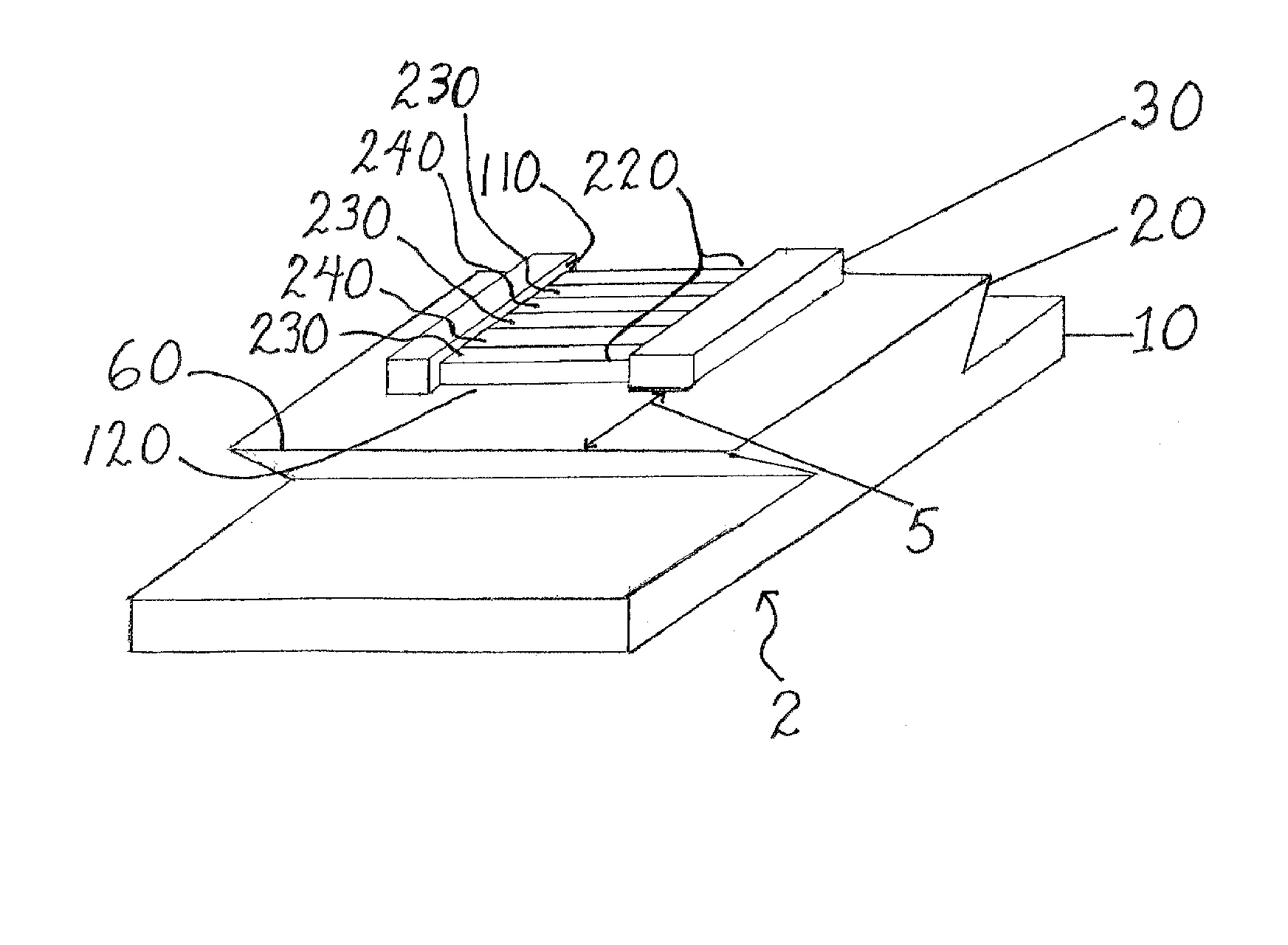
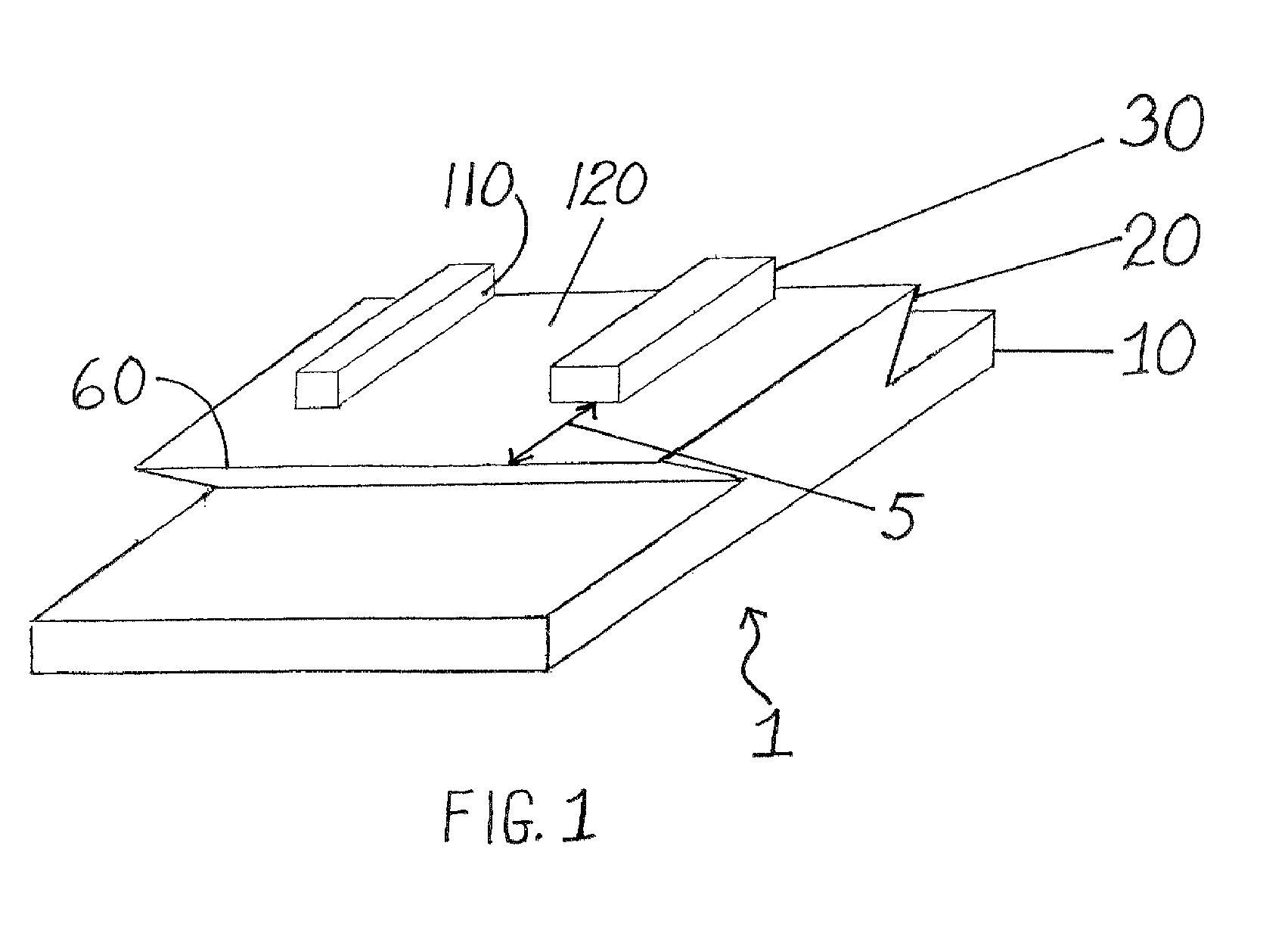
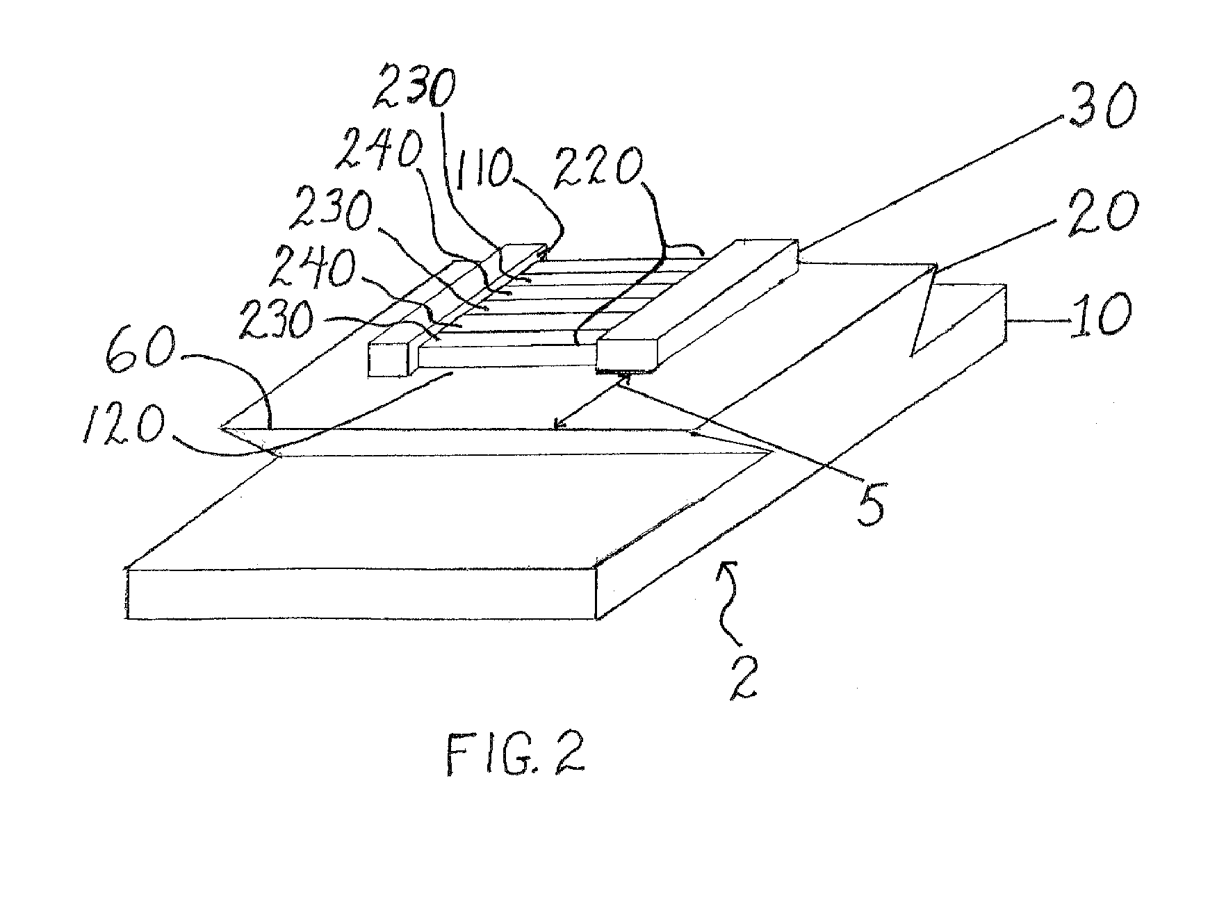
[0011]The first topographic “phase pinning” pattern is formed so as to contain a mesa having an edge. Alternatively, the first topographic “phase pinning” pattern can be in the shape of a ledge, wherein the ledge comprises an overhang. The surface comprising both the first topographic “phase pinning” pattern and the second topographic “guiding” pattern is then made energetically neutral by methods known to one of ordinary skill in the art. An energetically neutral surface, which includes at least the sidewalls and the bottom of the trench patterns, provides for the later formation of lamellar micro-domains from a self assembling di-block copolymer. The lamellar micro-domains, which have alternating blocks of different compositions, are substantially perpendicular to the sidewalls of the trench patterns.
[0012]The layer further removed from the substrate is a second topographic “guiding” pattern. The second topographic “guiding” pattern resides substantially on top of the first topographic pattern, thus forming a composite comprising substrate / first topographic pattern / second topographic pattern. The second topographic pattern comprises at least one trough. The at least one trough can have a shape of a line, an arc, an angle, a combination thereof or the like. The at least one trough contains at least one open end. Thus, the at least one trough cannot be completely closed off like a box structure. Preferably, the at least one trough contains an opening at both ends of the trough; that is, the trough is open at both ends. Open end(s) of the at least one trough are positioned close enough to the first topographic “phase pinning” pattern so that one block of a di-block copolymer can be pinned to the edge. This allows positioning the starting point of line-forming lamellar micro-domains in the trough. The lateral position (registration) of the lamellae is thus controlled.

Problems solved by technology

This desire for large-scale integration has led to a continued shrinking of the circuit dimensions and features of the devices.
For example, aberrations, focus, and proximity effects in the use of light limit the ability to fabricate features having reduced linewidth.
With IC design expected to require sub-50 nm interconnects, it is apparent that conventional lithography cannot meet this design requirement.

Method used


Image

  • Method of positioning patterns from block copolymer self-assembly
  • Method of positioning patterns from block copolymer self-assembly
  • Method of positioning patterns from block copolymer self-assembly

Examples


Embodiment Construction

[0019]A monomer as used herein is a molecule that can undergo polymerization thereby contributing constitutional units to the essential structure of a macromolecule, an oligomer, a block, a chain and the like.

[0020]A polymer as used herein is a macromolecule comprising multiple repeating smaller units or molecules (monomers) bonded together covalently. The polymer may be a natural polymer or a semi-synthetic polymer or a fully synthetic polymer.

[0021]A copolymer as used herein is a polymer derived from more than one chemical species of smaller unit or monomer.

[0022]A block copolymer as used herein is a copolymer that comprises more than one species of monomer, wherein the monomers are present in homogenous larger units or blocks. Each block of the specific monomer comprises repeating sequences of only that monomer, uninterrupted by other monomers. A formula (1) representative of a block copolymer is shown below:

—(A)a—(B)b—(C)c—(D)d—  (1)

wherein A, B, C and D represent different mono...


PUM

PropertyMeasurementUnit
Dynamic viscosityaaaaaaaaaa

Abstract

A method of controlling both alignment and registration (lateral position) of lamellae formed from self-assembly of block copolymers, the method comprising the steps of obtaining a substrate having an energetically neutral surface layer comprising a first topographic “phase pinning” pattern and a second topographic “guiding” pattern; obtaining a self-assembling di-block copolymer; coating the self-assembling di-block copolymer on the energetically neutral surface to obtain a coated substrate; and annealing the coated substrate to obtain micro-domains of the di-block copolymer.

Description

BACKGROUND OF THE INVENTION[0001]The present invention relates generally to the fabrication of integrated circuits and, more particularly, relates to the fabrication of integrated circuits by a patterning process which uses self-assembling polymers.[0002]The semiconductor industry has a need to manufacture integrated circuits (ICs) with higher and higher densities of devices on a smaller chip area to achieve greater functionality and to reduce manufacturing costs. This desire for large-scale integration has led to a continued shrinking of the circuit dimensions and features of the devices.[0003]The ability to reduce the sizes of structures such as gates in field effect transistors (FETs), is driven by lithographic technology which is, in turn, dependent upon the wavelength of light used to expose the photoresist. In current commercial fabrication processes, optical devices expose the photoresist using light having a wavelength of 193 nm (nanometers). Research and development laborat...

Claims


Application Information

Patent Timeline
IPC IPC(8): B05D3/02
CPCB81C1/00031H01L21/0337B82Y30/00B81C2201/0149B33Y80/00B05D3/02
Inventor KIM, HO-CHEOLRETTNER, CHARLES T.PARK, SANG-MIN
Owner TAIWAN SEMICON MFG CO LTD
Learn More