Digital television broadcast signal receiver

a digital television and receiver technology, applied in the field of digital television broadcast signal receivers, can solve the problems of only receiving radio waves, broadcast stations, business, etc., and achieve the effects of accurate storage, quick and accurate adjustment, and smooth scan procedur

Inactive Publication Date: 2009-07-07
FUNAI ELECTRIC CO LTD
View PDF3 Cites 5 Cited by
  • Summary
  • Abstract
  • Description
  • Claims
  • Application Information

AI Technical Summary

Benefits of technology

[0011]An object of the present invention is to provide a digital TV signal receiver that can quickly start the readjustment of antenna directions for all channels because it can automatically detect the misalignment of antennas and obtain the latest direction information quickly and accurately, and that enables the acquisition of the best reception condition at all times by removing unnecessary antenna searches and saving meaningless scan time.
[0013]By such a configuration, the best receiving direction of antennas can be readjusted quickly and accurately, and the best reception condition can always be obtained because, when the antenna direction is readjusted, the influence of stored direction data can be completely removed, the scan procedure can also be performed smoothly, and the receiving direction data newly obtained after scanning can accurately be stored. In addition, the update of the stored data in the memory can be reliably performed, and then the amount of memory can be reduced. Therefore, meaningless time and effort will not be spent on the readjustment of the antenna directions, and proper reception can be provided quickly.

Problems solved by technology

On the other hand, it also has a disadvantage in that it can receive only radio waves from a given broadcast station because of these strong directional characteristics.
However, in countries like the U.S., broadcast stations, which are relatively easily to start as a new business, often go bankrupt.
Therefore, a channel that could not be received before may become newly receivable, or one that could be received before may become unreceivable.
Even in the case in which a multi-directional antenna that requires less time to switch the receiving direction is connected to a digital TV broadcast signal receiver equipped with the auto-scan function, since the interval to output control signals for switching the receiving direction is long, the time required to determine the best receiving direction of the TV broadcast signals of a selected channel becomes very long, which irritates users.
However, since, in the case of using an in door antenna, there is a possibility that a user might change the installation location of an antenna or accidentally change the direction of an installed antenna physically, trouble such as TV signals becoming unreceivable can easily occur.
When signals cannot be received on Channel X, there is a problem: even though the directions of antennas are not actually misaligned, some time is wasted on meaningless operations, such as unnecessary scanning of all channels, if there is no response to determine whether only Channel X becomes unreceivable for some reason or whether there is a misalignment of all antenna directions.
In addition, when the antenna direction is reset, there is a problem: since the stored direction information includes receiving direction information, receiving signal strength information, and additional information (such as the ADD flag, showing that the receiving signal strength is higher than the standard level), and the direction of an antenna is controlled according to the stored information, the correct antenna direction control is interfered with, as in a disruption of antenna direction adjustment in which the correct direction cannot be set, if old direction information is left without being updated.

Method used


Image

  • Digital television broadcast signal receiver
  • Digital television broadcast signal receiver
  • Digital television broadcast signal receiver

Examples


Embodiment Construction

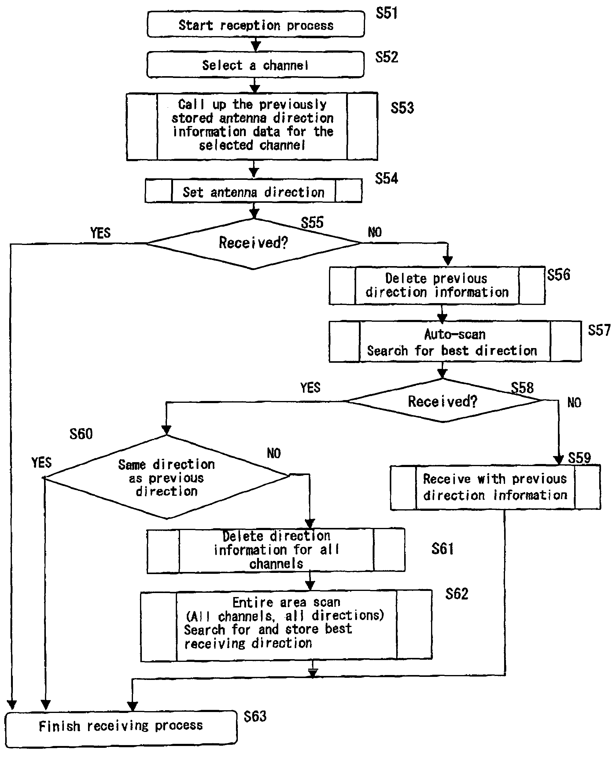
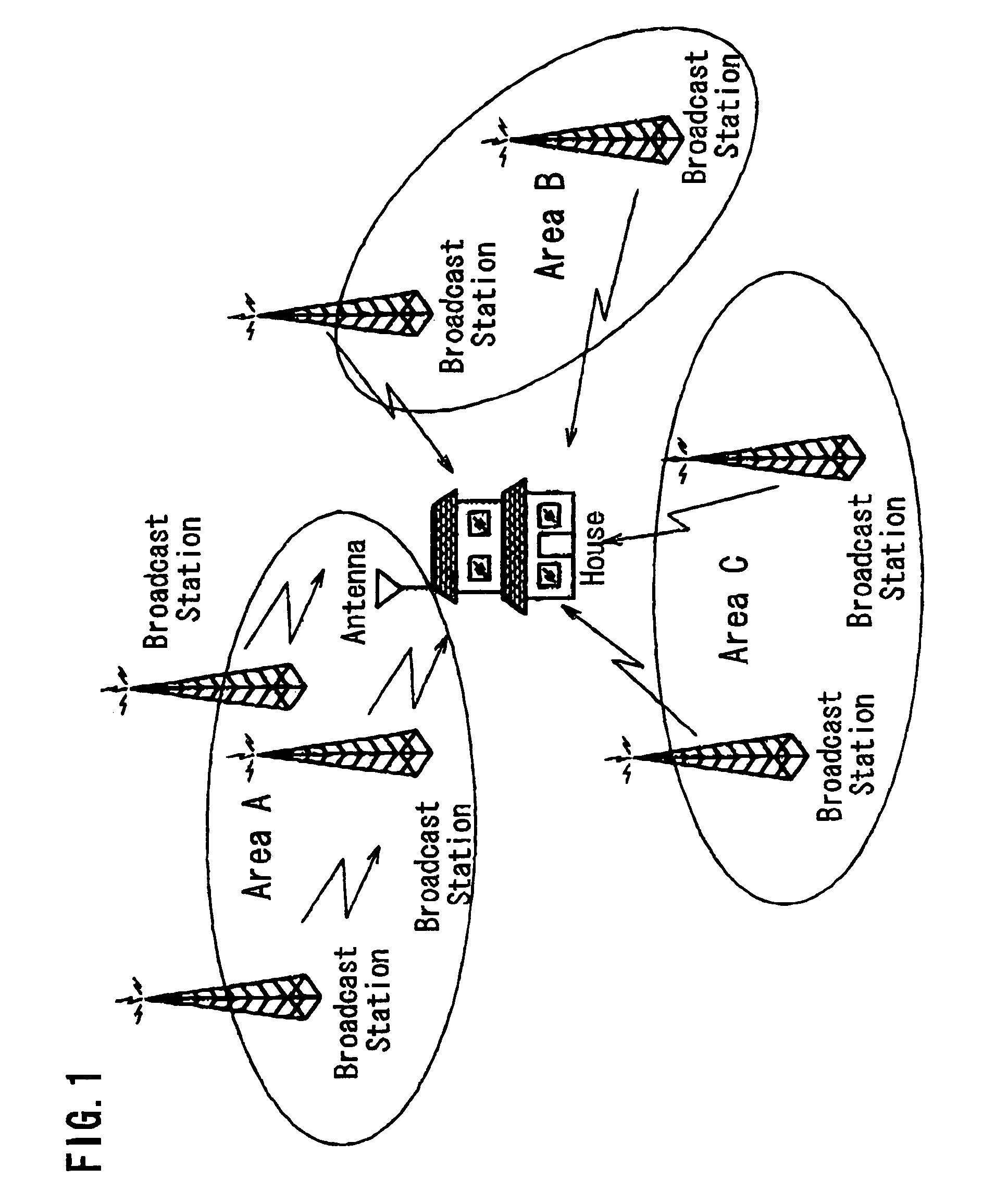
[0021]A digital TV broadcast signal receiver relating to an embodiment of the present invention is explained with reference to the figures. FIG. 1 shows a state in which a user receives TV broadcast signals at home. In areas where the digital (ground wave) TV broadcast is provided, if the strength of received digital TV broadcast signals is over a certain threshold, a certain quality of images can be obtained by correction, etc. Therefore, as shown in FIG. 1, TV programs can he watched by receiving the TV broadcast signals which are sent from broadcast stations that exist in multiple locations, such as area A, area B, and area C. Supporting these situations, a multi-directional antenna called a smart antenna, which has multiple receiving directions, comes into practical use.

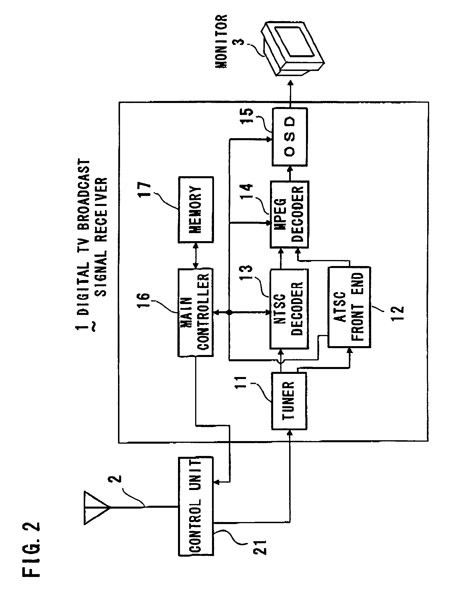
[0022]The digital TV broadcast signal receiver can also receive analog TV broadcast signals and, as well as the digital TV broadcast signals, perform the lean and best receiving direction control while confirming...


PUM


Abstract

In multi-directional antennas connected to a digital TV broadcast signal receiver, when a receiving channel is selected, if an antenna is set to the same direction as a previously stored direction, and signals cannot be received, the previously stored direction data is deleted, and if the best receiving direction is searched by the auto-scan, and a receivable direction does not match the previously stored receiving direction, the stored direction information is all deleted, the entire area scan is performed over all directions for all channels, and a new receiving direction for each channel is determined by the obtained best receiving direction. By doing this, when signals becomes unreceivable on a given channel while receiving them with a direction-adjusted smart antenna, meaningless time for adjusting directions is saved and the best reception condition is always obtained quickly by detecting the direction misalignment as soon as possible and updating the direction data on all other channels as well in the early stages.

Description

BACKGROUND OF THE INVENTION[0001]1. Field of the Invention[0002]The present invention relates to a digital television broadcast signal receiver to receive digital television broadcast signals, such as ATSC (Advanced Television Systems Committee).[0003]2. Description of the Related Art[0004]Since, in North America where the ATSC digital television broadcast (TV broadcast) is provided, large cities are located in plain fields, and TV broadcast signals come from various directions from the viewpoint of users who receive TV broadcast signals sent from around each city, users need to adjust the direction of antennas towards the broadcast station which broadcasts programs they wish to watch. Therefore, a multi-directional antenna is coming into practical use. A general antenna for ground wave television broadcasts has a shape called a Yagi antenna and is characterized by the ability to receive even weak radio waves because of strong directional characteristics. On the other hand, it also ...

Claims


Application Information

Patent Timeline
Patent Type & Authority Patents(United States)
IPC IPC(8): H04N7/20H04B1/16H04N5/44
CPCH01Q1/1257
Inventor TAKAGI, TOSHIHIROMIYAGAWA, TATSUO
Owner FUNAI ELECTRIC CO LTD
Why Eureka
Try Eureka