
Electrophotographic photoreceptor, and image forming method, apparatus and process cartridge therefor using the photoreceptor

a photoreceptor and electrophoresis technology, applied in the direction of electrophoresis, electrographic process, electrographic process using charge pattern, etc., can solve the problems of abnormal images such as image density deterioration, background fouling, and mechanical abrading of organic photoreceptors with image developers, etc., to achieve good cleanability, stable electrical properties, and high durability

Inactive Publication Date: 2009-07-07
RICOH KK
View PDF116 Cites 7 Cited by
  • Summary
  • Abstract
  • Description
  • Claims
  • Application Information

AI Technical Summary

Benefits of technology

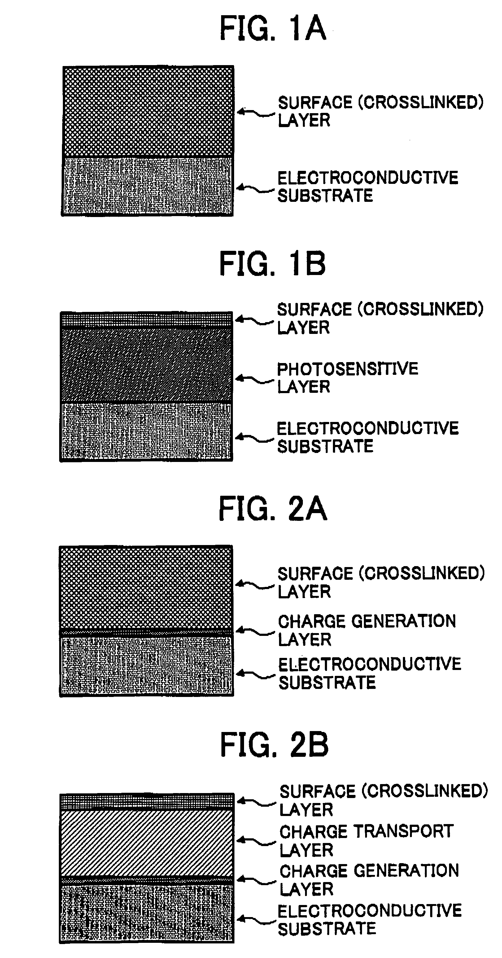
The present invention provides an electrophotographic photoreceptor with good cleanability, durability, and stable electrical properties for long periods. The photosensitive layer has good surface smoothness, abrasion resistance, and electrical properties. The crosslinked layer of the photoreceptor includes a radical polymerizing monomer, a radical polymerizing compound, and a reactive silicone compound. The reactive silicone compound has a radical polymerizing functional group, such as an acryloyloxy or methacryloyloxy group. The three or more functional groups of the monomer are preferably from the acryloyloxy or methacryloyloxy groups. The invention also provides an image forming method, apparatus, and process cartridge using the photoreceptor.

Problems solved by technology

In this respect, the organic photoreceptor has a soft surface layer mainly formed from a low-molecular-weight charge transport material and an inactive polymer, and therefore the organic photoreceptor has a drawback of being mechanically abraded with an image developer and a cleaner when used repeatedly in the electrophotographic process.
Unfortunately, this also accelerates abrading photoreceptors.
Such abrasions of photoreceptors deteriorate electrical properties such as sensitivities and chargeabilities, and cause abnormal images such as image density deterioration and background fouling.
The photoreceptor using charge transport polymer material of (2) and the photoreceptor having a surface layer wherein an inorganic filler is dispersed of (3) have abrasion resistance to some extent, but which is not fully satisfactory.
The photoreceptors of (1) to (3) do not have satisfactory electrical and mechanical durability.
This causes deterioration of mechanical strength of the photoreceptor.
Further, since the hardened multifunctional acrylate monomer is reacted in a surface layer including a polymer binder, the monomer is not fully hardened.
Thus, it is not soluble with the binder and fails to cause a surface concavity and convexity of the resultant photoreceptor due to the phase separation when hardened, resulting in defective cleanability.
This causes a surface concavity and convexity of the resultant photoreceptor due to the phase separation when crosslinked, resulting in defective cleanability.
Further, the binder resin prevents the monomer from hardening, and the monomer used in the photoreceptor is a difunctional monomer which has few functional groups and does not have a sufficient crosslinked density.
Therefore, the abrasion resistance of the resultant photoreceptor is not satisfactory.
Even when a binder resin reacts with a charge transport material, since the monomer and binder resin have few functional groups, it is difficult to have both a bonding amount of the charge transport material and a crosslinked density.
The resultant photoreceptor, therefore, does not have sufficient electrical properties and abrasion resistance.
However, since the photosensitive layer includes a bulky positive hole transport material having two or more chain polymerizing functional groups, a distortion appears in the hardened compound and internal stress increases to cause roughness and cracking in the surface layer, resulting in insufficient durability of the resultant photoreceptor.
However, since these photoreceptors include a lubricant in the photosensitive layer having an insufficient abrasion resistance, adherence of various materials can be prevented in initial stages, but cannot be maintained for long periods.
Therefore, deterioration of resistivity is inevitable due to a water-absorbing property of the electroconductive particulate metal oxide, and the photoreceptor produces blurred images.
However, since the photosensitive layer includes a bulky positive hole transport material having two or more chain polymerizing functional groups, a distortion appears in the hardened compound and the internal stress increases to cause roughness and cracking in the surface layer, resulting in poor durability.
In addition, the distortion in the photosensitive layer enlarges concavity and convexity on the surface of the resultant photoreceptor, resulting in a smaller contact area between the photoreceptor and contact members.
Accordingly, even a conventional photoreceptor having a crosslinked photosensitive layer chemically bonded with a charge transportable structure fails to have sufficient overall characteristics.
Although a variety of inventions to lower the surface energy have been made, these changes do not satisfactory improve the durability, electrical properties and other properties.

Method used


Image

  • Electrophotographic photoreceptor, and image forming method, apparatus and process cartridge therefor using the photoreceptor
  • Electrophotographic photoreceptor, and image forming method, apparatus and process cartridge therefor using the photoreceptor
  • Electrophotographic photoreceptor, and image forming method, apparatus and process cartridge therefor using the photoreceptor

Examples


example 1

[0222]An undercoat coating liquid, a charge generation coating liquid and charge transport coating liquid, which have the following formulations, were coated in this order on an aluminium cylinder by a dip coating method and dried to prepare a photoreceptor 1 having an undercoat layer of 3.5 μm thick, a CGL of 0.2 μm thick, a CTL of 23 μm thick.

[0223]

Undercoat layer coating liquidTitanium dioxide powder400Melamine resin65Alkyl resin1202-butanone400CGL coating liquidBisazo pigment having the following formula:12Bisphenol Z-type Polycarbonate52-butanone200Cyclohexanone400CTL coating liquidBisphenol Z-type Polycarbonate10CTM having the following formula:10Tetrahydrofuran100

[0224]The CTL was further coated with a crosslinked surface layer coating liquid having the following formulation by a spray coating method.

[0225]

Crosslinked surface layer coating liquidRadical polymerizing monomer having three or more95functional groups without a charge transporting structureTrimethylolpropanetriacr...

example 2

[0228]The procedure for preparation of the electrophotographic photoreceptor in Example 1 was repeated to prepare an electrophotographic photoreceptor with the exception of changing the Reactive silicone compound having a radical polymerizing functional group to:

[0229]Mono-terminal methacryl-modified polysiloxane

[0230]X-22-174DX from Shin-Etsu Chemical Co., Ltd.

[0231]having a molecular weight of 4,600,

[0232]a viscosity of 60 mm2 / s,

[0233]a refraction index at 25° C. of 1.407, and

[0234]a specific gravity at 25° C. of 0.97.

example 3

[0235]The procedure for preparation of the electrophotographic photoreceptor in Example 1 was repeated to prepare an electrophotographic photoreceptor with the exception of changing the Reactive silicone compound having a radical polymerizing functional group to:

[0236]Polydimethylsiloxane having

[0237]a polyether-modified acrylic group

[0238]BYK-UV3500 from BYK Chemie Japan K.K


PUM

PropertyMeasurementUnit
viscosityaaaaaaaaaa
viscosityaaaaaaaaaa
primary particle diameteraaaaaaaaaa

Abstract

An electrophotographic photoreceptor including an electroconductive substrate and a photosensitive layer overlying the electroconductive substrate. An outermost layer of the electrophotographic photoreceptor is a crosslinked layer including a radical polymerizing monomer having three or more functional groups without a charge transporting structure. The outermost layer also includes a radical polymerizing compound having one functional group with a charge transporting structure and a reactive silicone compound having a radical polymerizing functional group.

Description

CROSS-REFERENCE TO RELATED PATENT DOCUMENTS[0001]This document claims priority and contains subject matter related to Japanese Patent Application No. 2003-329178 filed on Sep. 19, 2003, incorporated herein by reference.BACKGROUND OF THE INVENTION[0002]1. Field of the Invention[0003]The present invention relates to an electrophotographic photoreceptor, and to an image forming method, an image forming apparatus and a process cartridge using the photoreceptor.[0004]2. Discussion of the Background[0005]Organic photoreceptors (OPCs) are widely used instead of inorganic photoreceptors for copiers, facsimiles, laser printers because of their superior performances and advantages. Specific advantages include (1) optical properties such as the ability to absorb a wide range of light and the ability to absorb a large amount of light; (2) electrical properties including high sensitivity and stable chargeability; (3) materials; (4) good manufacturability; (5) low cost; (6) non-toxicity, etc.[000...

Claims


Application Information

Patent Timeline
Patent Type & Authority Patents(United States)
IPC IPC(8): G03G5/047G03G5/147G03G5/05G03G5/06G03G5/07
CPCG03G5/0542G03G5/0546G03G5/0578G03G5/0589G03G5/0592G03G5/0614G03G5/14795G03G5/14734G03G5/14739G03G5/14773G03G5/14786G03G5/14791G03G5/071G03G5/072G03G5/0732G03G5/074G03G5/0745
Inventor YANAGAWA, YOSHIKIIKUNO, HIROSHILI, HONGGUONAGAI, KAZUKIYOTAMURA, HIROSHISUZUKI, TETSURO
Owner RICOH KK
Learn More