
Detection and monitoring of partial discharge of a power line

a technology of partial discharge and monitoring, applied in the direction of power distribution line transmission, fault location, instruments, etc., can solve the problems of affecting cables, surge arrestors, other high-voltage devices, noise generation of faulty overhead insulators, etc., and not being practical for permanent deploymen

Active Publication Date: 2009-05-12
ERICSSON INC
View PDF19 Cites 51 Cited by
  • Summary
  • Abstract
  • Description
  • Claims
  • Application Information

AI Technical Summary

Benefits of technology

Enables effective, continuous monitoring of power line conditions, accurately detecting PD even in noisy environments and communicating data to a central location, reducing false positives from external interference and improving maintenance efficiency.

Problems solved by technology

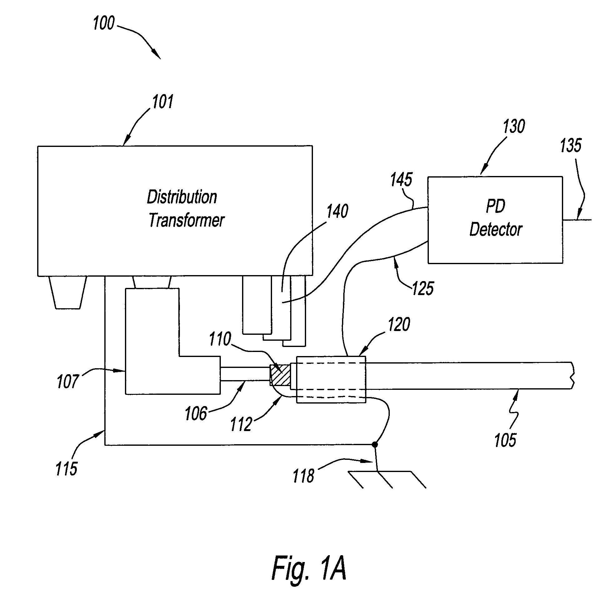
PD may afflict cables, connectors, surge arrestors, and other high voltage devices.
Faulty overhead insulators may also generate noise with frequency and phase characteristics similar to PD.
These techniques are generally employed after a cable is suspected of PD, and may not be practical for permanent deployment, due to lack of an ability to readily communicating the information to some central location or due to excessive cost.
A disadvantage of some of these techniques is their requirement that PD signals be the strongest signals present, and so, such techniques may not function well in a field environment that includes strong radio signals that are picked up by the cable.

Method used


Image

  • Detection and monitoring of partial discharge of a power line
  • Detection and monitoring of partial discharge of a power line
  • Detection and monitoring of partial discharge of a power line

Examples


Embodiment Construction

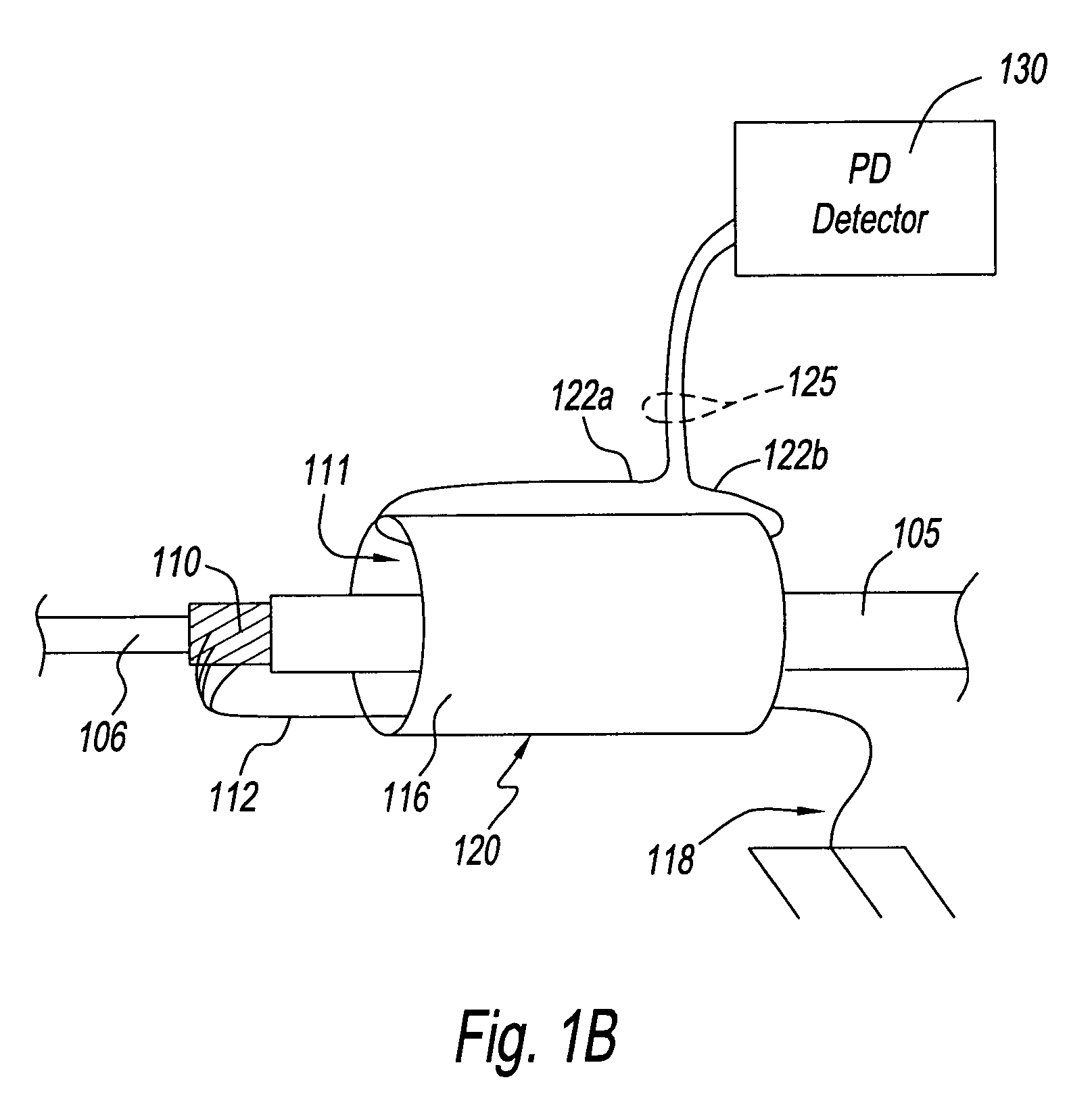
[0024]In a power line communication system, power frequency is typically in a range of 50-60 Hertz (Hz) and a data communications signal frequency is greater than about 1 MHz, and typically in a range of 1 MHz-50 MHz. A data coupler for power line communications couples the data communications signal between a power line and a communication device such as a modem.

[0025]An example of such a data coupler is an inductive coupler that includes a core, and a winding wound around a portion of the core. The core is fabricated of a magnetic material and includes an aperture. The inductive coupler operates as a transformer, and is situated on a power line such that the power line is routed through the aperture and serves as a primary winding of the transformer, and the winding of the inductive coupler serves as a secondary winding of the transformer. The data communications signal is coupled between the power line and the secondary winding via the core. The secondary winding is coupled, in t...


PUM


Abstract

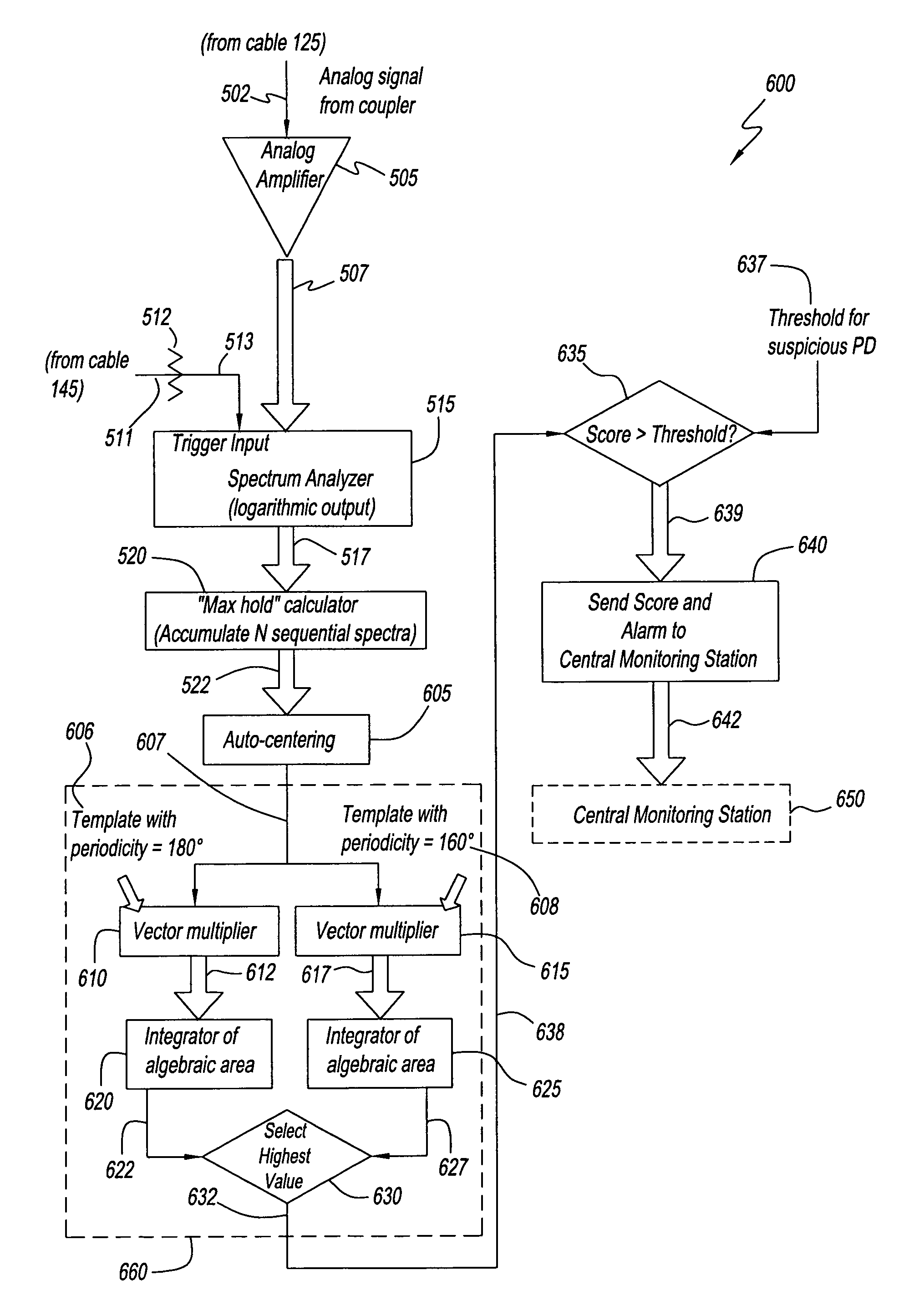
There is provided a method that includes (a) determining a characteristic of a fundamental spectral component of a spectrum of a power spectrum of noise on a power line, and (b) determining a condition of the power line based on the characteristic.

Description

CROSS-REFERENCE TO RELATED APPLICATIONS[0001]The present application is claiming priority of U.S. Provisional Patent Application No. 60 / 819,072, filed Jul. 7, 2006, the content of which is herein incorporated by reference.BACKGROUND OF THE INVENTION[0002]1. Field of the Invention[0003]The present invention relates to automated monitoring of the condition of medium and high voltage cables and insulators in an electrically noisy environment, and more particularly, to alternating current (AC) power line discharge. The present invention is particularly advantageous in a case where a power line communications infrastructure is available to carry monitoring data to a central location.[0004]2. Description of the Related Art[0005]Partial discharge (PD) is a phenomenon that occurs in insulation that has sustained damage, such as through aging, physical damage, or exposure to excessively high electric fields. PD may afflict cables, connectors, surge arrestors, and other high voltage devices. ...

Claims


Application Information

Patent Timeline
Patent Type & Authority Patents(United States)
IPC IPC(8): G01R31/12H01H9/50
CPCG01R31/1272H04B3/54H04B2203/5495G01R23/00G01R31/08G01R31/12
Inventor CERN, YEHUDA
Owner ERICSSON INC
Learn More