
Releasable highway safety structures

a highway safety and release mechanism technology, applied in roadway safety arrangements, construction, roads, etc., can solve the problems of inability to control or control the actual release mode (the way that the actual release is accomplished), the actual release mode is relatively unmanaged, and the combination of various types of loads and geometric details is not uniform. achieve the effect of adequate safety, maximum strength of the guardrail system, and stable and predictable respons

Inactive Publication Date: 2009-05-12
OCHOA CARLOS M
View PDF64 Cites 33 Cited by
  • Summary
  • Abstract
  • Description
  • Claims
  • Application Information

AI Technical Summary

Benefits of technology

[0014]A technical advantage of the present invention includes its ability to consistently release the guardrail or other vehicle impact member in a prescribed manner from substantially horizontal or vertical support members. This enhanced release permits the highway engineer to maximize the strength a guardrail system and provides for a more stable and predictable response during vehicle impacts with the system. Accordingly, the guardrail system may withstand significant forces of impact while maintaining adequate safety to passengers, bystanders, and vehicles.
[0015]In one embodiment, forces acting largely parallel to the long axis of the guardrail act primarily on one portion, while forces acting perpendicular to the face of the guardrail act primarily on a different portion, where paths are provided for release in a prescribed and repeatable load range.
[0016]In a particular embodiment, one or more different positioning members may be disposed longitudinally along the guardrail to assist with the installation or release process.
[0017]In another embodiment, the guardrail system includes end terminals and a cable guardrail, and the releasing member accomplishes the release of the cable from posts.
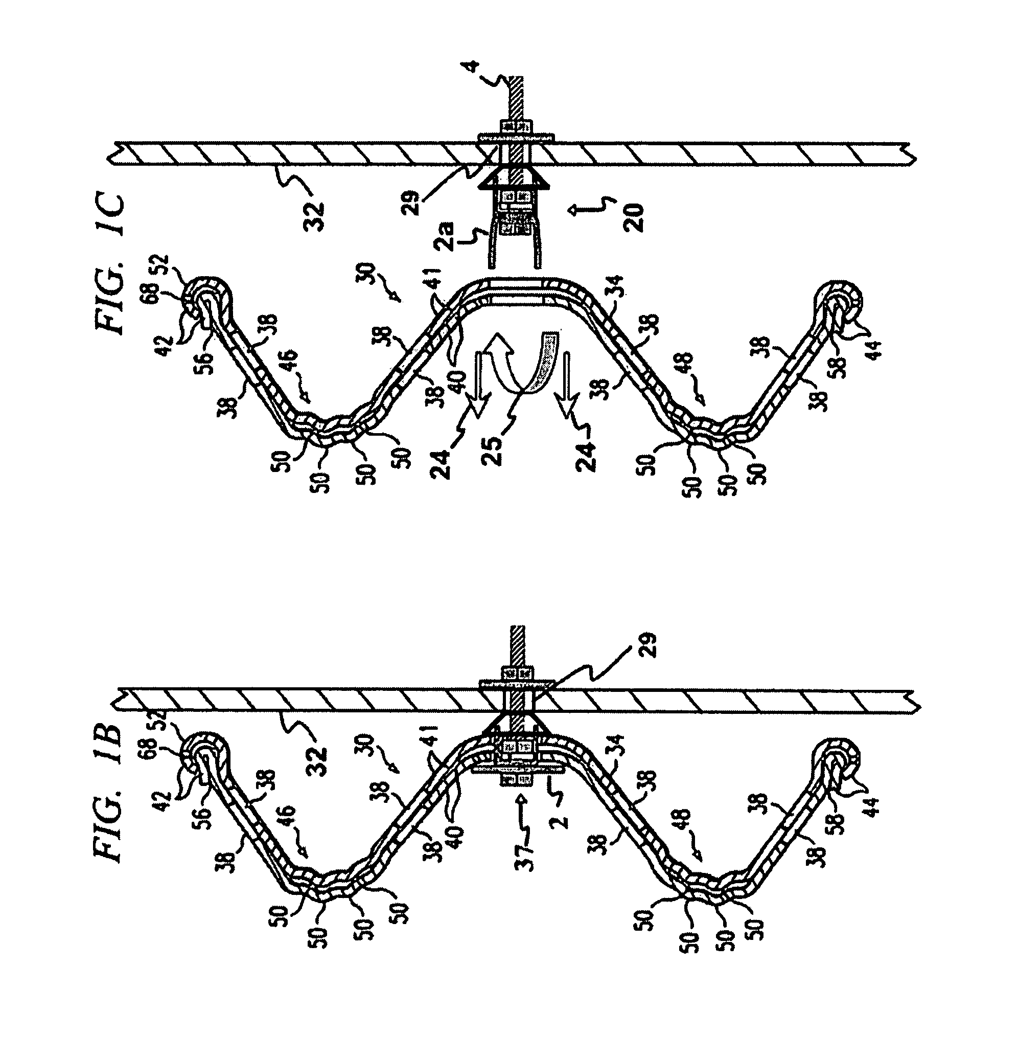
[0018]In one embodiment, a guardrail system is provided for installation along a roadway to redirect an errant vehicle, comprising a plurality of spaced support posts, a guardrail mounted on the plurality of support posts by a plurality of securing members, each securing member passing through a respective opening in the guardrail and an opening in a respective support post, a releasing member adjacent the securing member for releasing the guardrail from the support post during a vehicle impact, and a positioning member for centering the securing member within a central portion of one of the openings in the guardrail and the support post.
[0019]In another embodiment, a structural safety system to absorb energy from an errant vehicle includes at least one support, at least one vehicle impact absorbing member mounted to the support by a securing member passing through an opening in one of the vehicle impact absorbing member and the support, a releasing member for releasing the vehicle impact absorbing member from the support during a vehicle impact, the releasing member being adjacent the securing member or being an edge of the opening in the one of the vehicle impact absorbing member and the support, and a positioning member for centering the securing member within a central portion of the opening in one of the vehicle impact absorbing member and the support.

Problems solved by technology

For many years, various methods for the releasable mounting of guardrail system components have included the use of bolts that may fail (such as by stripping of the threads), break, or deform in a variety of relatively unreliable ways to accomplish the release of structural components.
With this, the actual release mode (the way that release is accomplished) has not been controlled or consistent, since it has not been unique or highly repeatable.
This means that there are extraneous combinations of various types of loads and geometric details that can and do occur.
Here again, the actual release mode is relatively unmanaged, and may vary widely.
One common problem with these mounting methods has been the failure to achieve a reliable and repeatable release of the guardrail from the post even under relatively ordinary circumstances.
When effective release fails to occur, the guardrail may remain attached to a post far beyond optimum timing during a crash event.
The result has been that errant vehicles struggle with the guardrail system in various ways during vehicle impacts rather than being smoothly redirected, simply due to inconsistent and relatively erratic release of components from each other during the vehicle impact event.
Significant suspension damage or occupant compartment deformation may also occur to the vehicle due to inadequate release.
The vehicle itself may actually be destabilized by the action of excessive forces that pile up in the guardrail system, thus causing the vehicle to overturn or to exit the system at relatively high angles of roll, pitch, or yaw that at the very least may adversely affect the driver's efforts to control the vehicle.
It has been a major problem that has plagued the worldwide highway safety industry since its inception over a hundred years ago.
Wide variations in release behavior have meant that important guardrail system forces remain largely unmanaged, making optimum and consistent system performance virtually impossible to achieve.
Variations include unpredictable and undesirable force combinations and pile-ups when release fails to occur.
While the symptoms of these problems have long been recognized, the problem itself has largely remained undefined and not well understood, even to the point of being somewhat regarded as “stochastic”, intractable and possibly unsolvable.
Increasingly stringent testing criteria have uncovered serious deficiencies in the capabilities of standard “W-beam” guardrail systems.
None of these proposed approaches has gained wide acceptance, since they have represented only partial solutions to individual symptoms of the problem of inadequate release.
Moreover, these solutions generally have had the effect of significantly increasing system complexity, cost, and installation time, without markedly increasing system capabilities.

Method used


Image

  • Releasable highway safety structures
  • Releasable highway safety structures
  • Releasable highway safety structures

Examples


Embodiment Construction

[0060]Preferred embodiments of the present invention and its advantages are best understood by referring now in more detail to the figures in which like numerals refer to like parts.

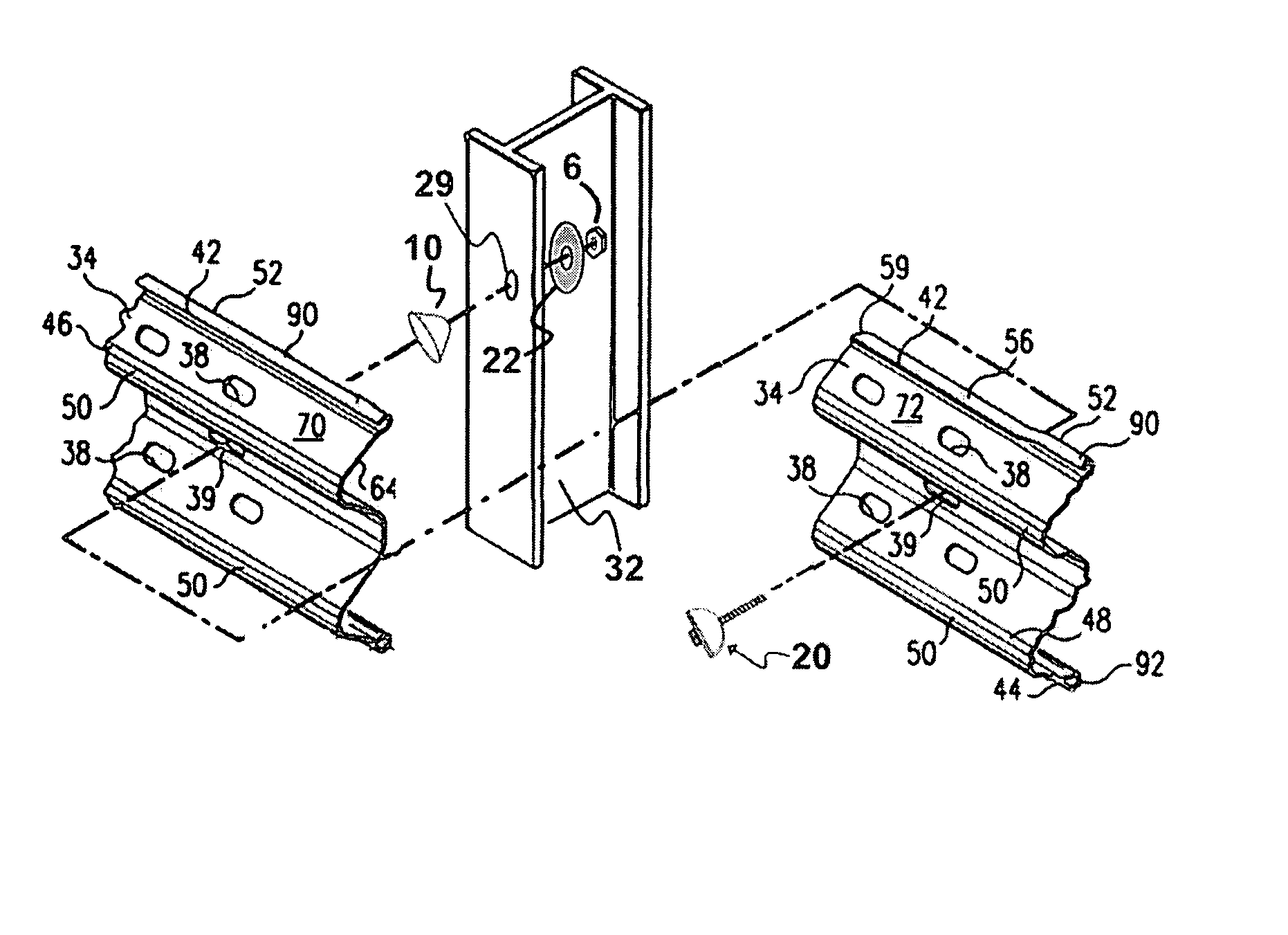
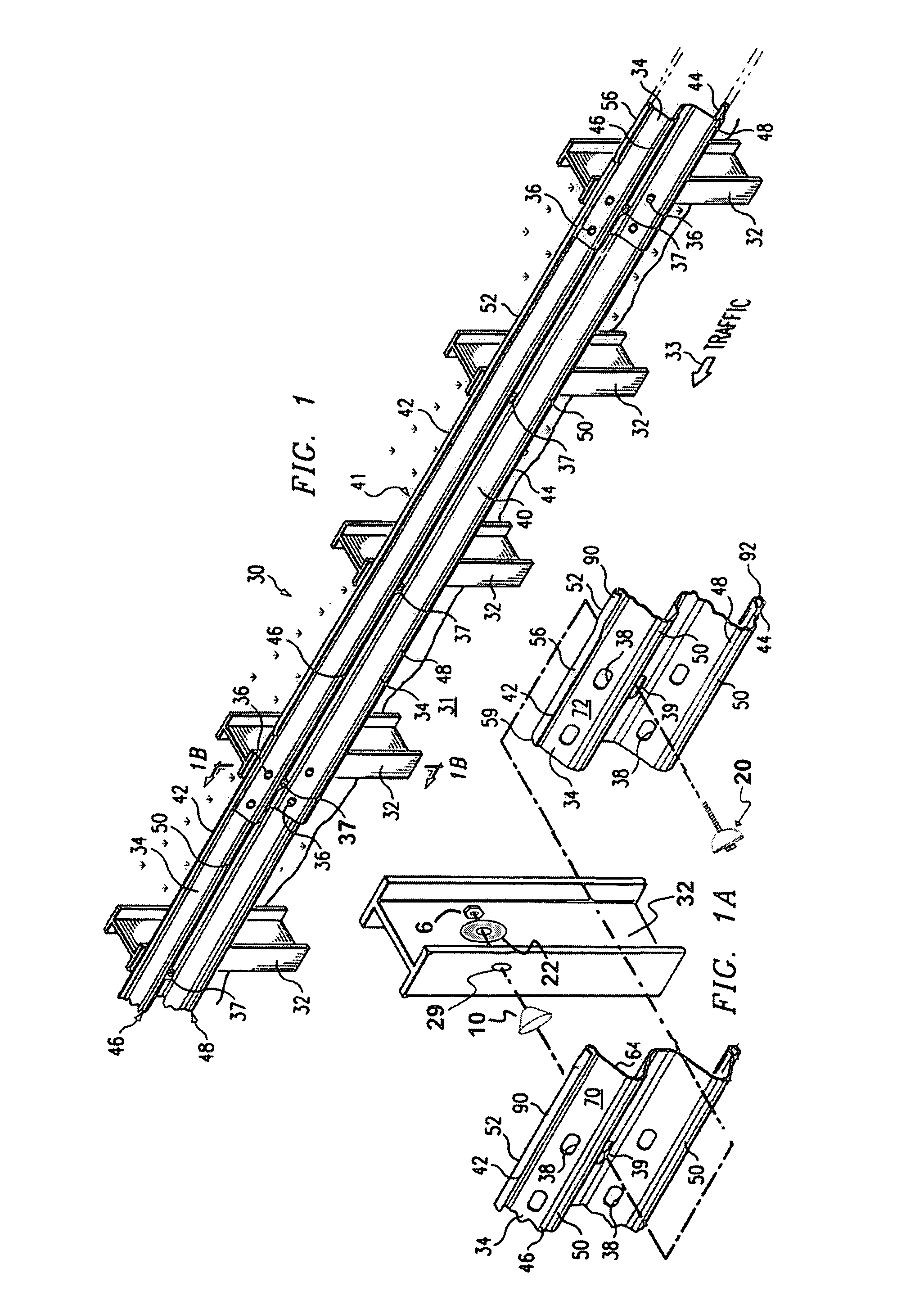
[0061]Referring to FIG. 1, guardrail system 30 is shown installed adjacent to roadway 31. The direction of oncoming traffic along roadway 31 is illustrated by directional arrow 33. Guardrail system 30 includes a plurality of support posts 32 anchored adjacent to roadway 31 by having a lower portion of each post below ground level, with a plurality of guardrail beams 34 attached to support posts 32 and secured by post bolts 37. For illustrative purposes, FIG. 1 includes one complete guardrail beam 34 and two partial sections of adjacent guardrail beams 34 to illustrate the splice connections between adjoining sections.

[0062]Guardrail system 30 may be installed along roadway 31 in order to prevent motor vehicles from leaving roadway 31 and to redirect vehicles away from hazardous areas without causing seri...


PUM


Abstract

Consistent and reliable releasing of a guardrail during a vehicle impact is enabled by a releasable fastener for safety structures along a highway. The release of secured components such as guardrail is controlled, and precise positional cooperation is provided between securing members and the guardrail. Forces may be attenuated to further optimize response.

Description

CROSS REFERENCE TO RELATED APPLICATION[0001]This application claims priority from and incorporates herein U.S. Provisional Application No. 60 / 589,193 filed Jul. 19, 2004.FIELD OF THE INVENTION[0002]The present invention relates generally to roadway safety devices and, more particularly, to the prescribed release of guardrail system components.BACKGROUND OF THE INVENTION[0003]A goal of roadway safety is to provide a forgiving roadway and adjacent roadside for errant motorists. Guardrails are employed along a roadside to accomplish multiple tasks. Upon vehicle impact, a guardrail must react as a decelerator and energy absorber to dissipate the kinetic energy of the vehicle. In addition, the guardrail acts as a mechanical guide to redirect the vehicle away from hazards during deceleration and to prevent the vehicle from leaving the road, being snagged by the guardrail system itself or from becoming airborne or rebounding excessively into traveled lanes of traffic.[0004]For many years, ...

Claims


Application Information

Patent Timeline
Patent Type & Authority Patents(United States)
IPC IPC(8): E01F15/02
CPCE01F15/0423E01F15/0438E01F15/146E01F15/143Y10T403/11F16B2200/63
Inventor OCHOA, CARLOS M.
Owner OCHOA CARLOS M
Learn More