Flat-aperture waveguide sidewall-emitting antenna

a waveguide and sidewall technology, applied in the field of antennas, can solve the problems of serious phase-front distortion (phase error), wave-reflection, and inability to use more conventional means such as pyramidal horns, and achieve the effect of shallow depth and large apertur

Inactive Publication Date: 2009-05-05
SCI APPL & RES ASSOCS
View PDF4 Cites 2 Cited by
  • Summary
  • Abstract
  • Description
  • Claims
  • Application Information

AI Technical Summary

Benefits of technology

[0005]A flat-aperture waveguide sidewall-emitting antenna in a compact low-profile configuration and with the capability of radiating a beam of extremely high-power microwave (HPM) pulses in a directional manner is provided. High-power microwave antennas are essential technologies to microwave-based directed energy weapons (DEW). The flat-aperture waveguide sidewall-emitting antenna is especially well-suited to high-power microwave operation because of its relatively large aperture, which distributes the output power evenly over a large area, thus reducing the risk of microwave-induced air-breakdown or surface-breakdown that would other wise impede proper operation and degrade output beam formation.
[0006]The conveyance of the input microwave power from one or more standard-size rectangular waveguides to a large aperture, in a low-profile package, is not practical with more conventional means such as a pyramidal horn. This is because serious phase-front distortion (phase error) and wave-reflection will occur if such a horn is made too short. In contrast to most alternative approaches for delivering such large apertures, the flat-aperture waveguide sidewall-emitting antenna possesses an unusually shallow depth especially advantageous for integration into fieldable military platforms. Such a low-profile (i.e., shallow depth) antenna is made possible by the novel employment of a specially-profiled, leaky-wave wire grill as the aperture comprising the sidewall of the waveguide, with the grill-wires oriented parallel to the electric field of the waveguide mode being conveyed.

Problems solved by technology

The conveyance of the input microwave power from one or more standard-size rectangular waveguides to a large aperture, in a low-profile package, is not practical with more conventional means such as a pyramidal horn.
This is because serious phase-front distortion (phase error) and wave-reflection will occur if such a horn is made too short.

Method used


Image

  • Flat-aperture waveguide sidewall-emitting antenna
  • Flat-aperture waveguide sidewall-emitting antenna
  • Flat-aperture waveguide sidewall-emitting antenna

Examples


Embodiment Construction

[0025]The detailed description set forth below is intended as a description of the presently preferred embodiment of the invention, and is not intended to represent the only form in which the present invention may be constructed or utilized. The description sets forth the functions and sequences of steps for constructing and operating the invention. It is to be understood, however, that the same or equivalent functions and sequences may be accomplished by different embodiments and that they are also intended to be encompassed within the scope of the invention.

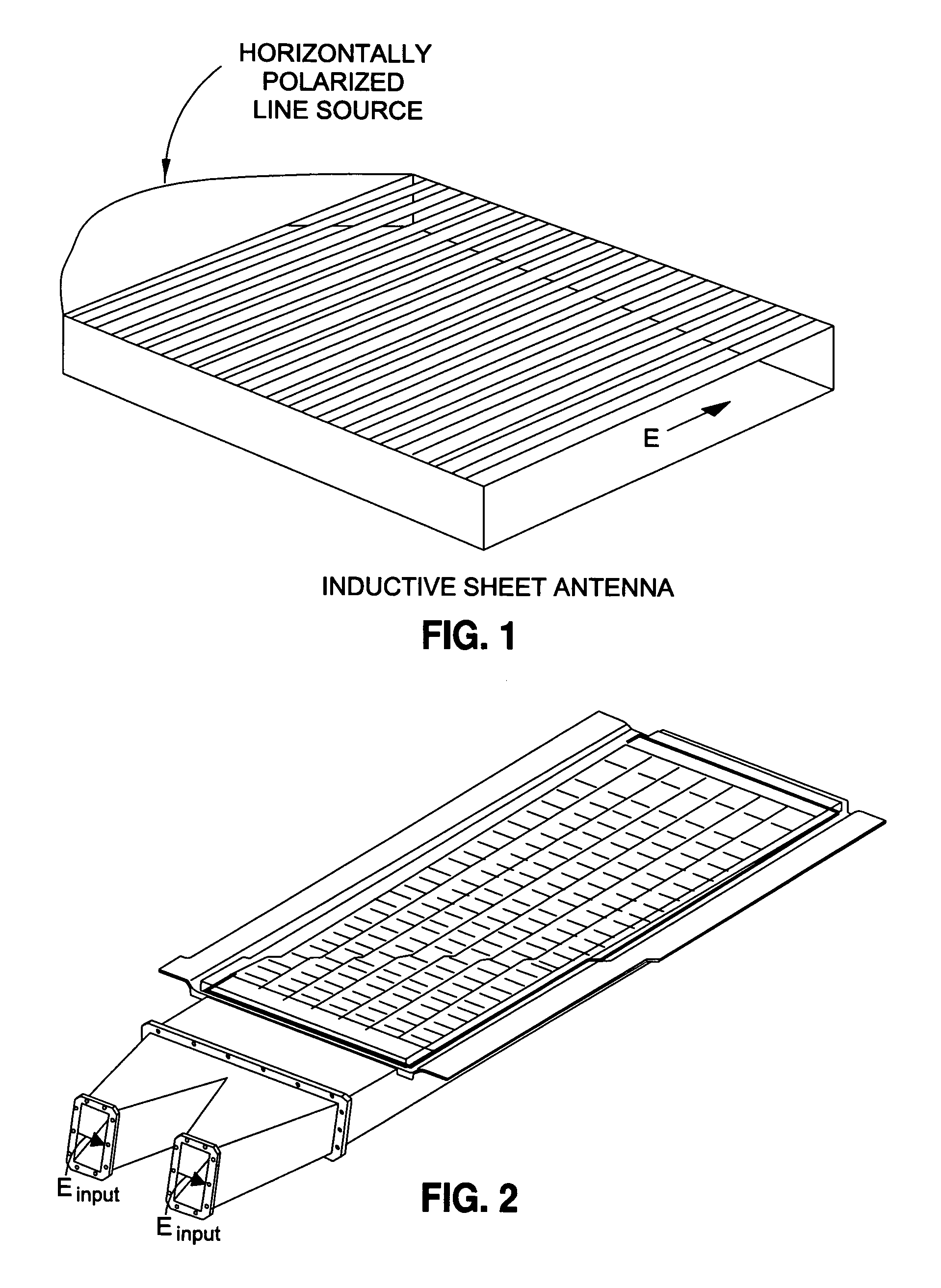
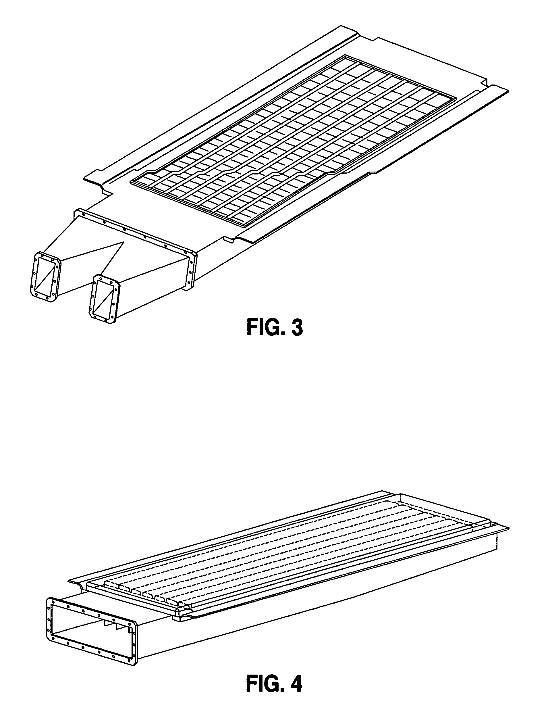
[0026]Referring now to the drawings, FIGS. 2 and 3 provide exterior views of an exemplary flat-aperture waveguide sidewall-emitting antenna as provided. Normally, the interior of the antenna is evacuated to high-vacuum during high-power microwave operation. A dielectric window is mounted to the antenna covering the aperture and an o-ring is applied to provide a vacuum-to-air seal. FIGS. 4 and 5 show additional views of the flat...


PUM


Abstract

A flat-aperture waveguide sidewall-emitting antenna in a compact low-profile configuration and with the capability of radiating a beam of extremely high-power microwave (HPM) pulses in a directional manner is provided. High-power microwave antennas are essential technologies to microwave-based directed energy weapons (DEW). The flat-aperture waveguide sidewall-emitting antenna is especially well-suited to high-power microwave operation because of its relatively large aperture, which distributes the output power evenly over a large area, thus reducing the risk of microwave-induced air-breakdown or surface-breakdown that would other wise impede proper operation and degrade output beam formation.

Description

CROSS-REFERENCE TO RELATED APPLICATIONS[0001]The present application claims priority to Provisional Patent Application Ser. No. 60 / 857,529, filed on Nov. 7, 2006, entitled FLAT-APERTURE WAVEGUIDE SIDEWALL-EMITTING ANTENNA.STATEMENT RE: FEDERALLY SPONSORED RESEARCH / DEVELOPMENT[0002]This invention was made with Government support under Contract No. FA9451-04-C-0155 awarded by the U.S. Air Force. The Government has certain rights in the invention.BACKGROUND[0003]The present invention relates in general to an antenna, and more particularly, to a flat-aperture waveguide sidewall-emitting antenna (FAWSEA) which provides a compact, low-profile configuration suitable for airborne or other fieldable platforms.[0004]The FAWSEA is properly categorized as a leaky-waveguide antenna of the fast-wave type. The physical principles behind the operation of the FAWSEA's waveguide and leaky-wire-grill are essentially the same as those reported decades ago by R. C. Honey as shown in FIG. 1. The design o...

Claims


Application Information

Patent Timeline
Patent Type & Authority Patents(United States)
IPC IPC(8): H01Q13/00
CPCH01Q13/22H01Q21/064
Inventor KOSLOVER, ROBERT
Owner SCI APPL & RES ASSOCS
Why Eureka
Try Eureka