
Press/push flash drive

a flash drive and push button technology, applied in the direction of individual entry/exit registers, coupling device connections, instruments, etc., can solve the problems of inability to duplicate or relocate in a manner consistent with traditional media, inherently limited by capacity restrictions, and limited number of “read-write” cycles

Inactive Publication Date: 2009-04-28
SUPER TALENT TECH CORP
View PDF3 Cites 61 Cited by
  • Summary
  • Abstract
  • Description
  • Claims
  • Application Information

AI Technical Summary

Benefits of technology

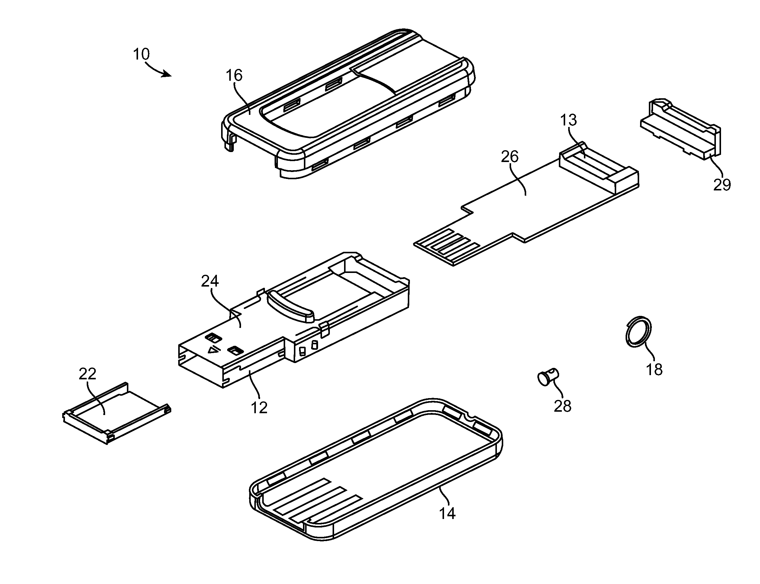
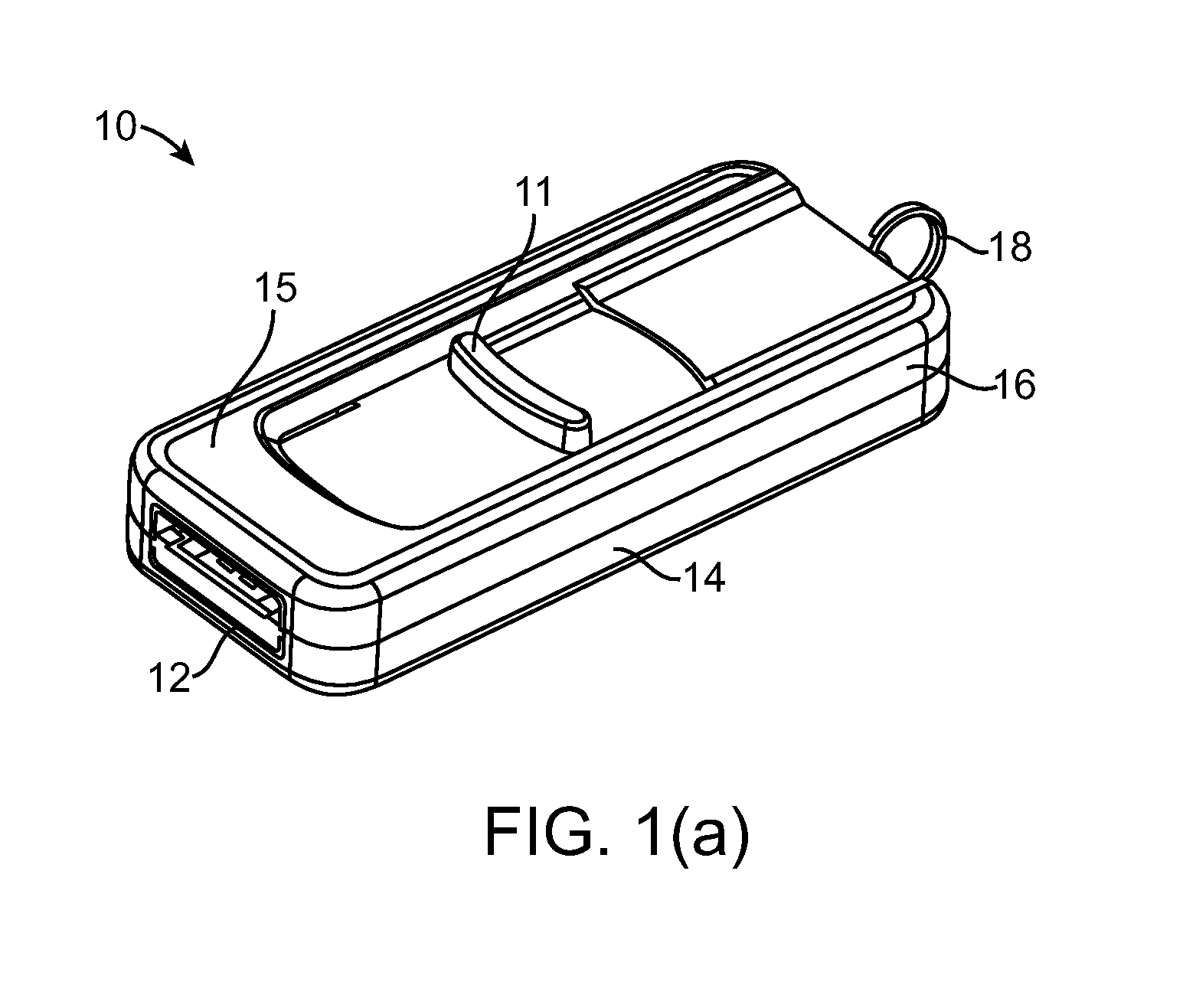
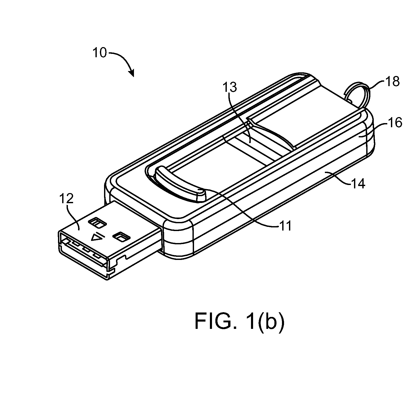
[0008]Briefly, an embodiment of the present invention includes a portable flash memory drive with a simplified mechanism, based upon the resilient properties of the material used to create the parts, for reliable extension and retraction of the device's interface plug. The portable flash memory drive is comprised of a metal housing (or case), a printed circuit board (PCB) assembly, PCB support, PCB assembly end cap, an upper, and lower housing, and in some embodiments a fingerprint sensor and / or key ring assembly. The press / push switch mechanism is located on either the side of the portable flash memory device, or the top; and relies upon the resilient properties of the material used to create the metal housing or end cap, to create a smooth, locking mechanism for the extension or retraction of the interface (i.e., USB or firewire) plug. The switching / locking mechanism relies upon grooves or notches within the material of the upper and / or lower housing for tracking and locking, coupled with protrusion tabs on the sliding components of the end cap or metal housing. Alternatively, in some embodiments of the present invention, a fingerprint sensor is also extended or retracted contemporaneously with the interface plug, and allows the end user to secure and unlock the data contained, in whole or in part, therein.

Problems solved by technology

Because of the digital format of these records and media, they can't be duplicated or relocated in a manner consistent with traditional media.
These formats were, however, inherently limited by capacity restrictions, limited numbers of “read-write” cycles, affected by slow read / write speeds, or easily ruined by temperature physical interaction with external elements.

Method used


Image

  • Press/push flash drive
  • Press/push flash drive
  • Press/push flash drive

Examples


Embodiment Construction

[0037]In the following description of the embodiments, reference is made to the accompanying drawings that form a part hereof, and in which is shown by way of illustration of the specific embodiments in which the invention may be practiced. It is to be understood that other embodiments may be utilized because structural changes may be made without departing from the scope of the present invention. It should be noted that the figures discussed herein are not drawn to scale and thicknesses of lines are not indicative of actual sizes.

[0038]In an embodiment of the present invention, a mechanically simplified press / push flash drive is disclosed. The press / push flash drive is comprised of a subassembly containing the necessary electronic devices, support materials, and two outer pieces that are pressed together to form a protective housing. The external switch on the press / push flash drive can be toggled between two distinct positions. When the switch is located in the position furthest f...


PUM


Abstract

Briefly, an embodiment of the present invention includes a portable flash memory drive with a simplified mechanism, based upon the resilient properties of the material used to create the parts, for reliable extension and retraction of the device's interface plug. The portable flash memory drive is comprised of a metal housing (or case), a printed circuit board (PCB) assembly, PCB support, PCB assembly end cap, an upper, and lower housing, and in some embodiments a fingerprint sensor and / or key ring assembly. The press / push switch mechanism is located on either the side of the portable flash memory device, or the top; and relies upon the resilient properties of the material used to create the metal housing or end cap, to create a smooth, locking mechanism for the extension or retraction of the interface (i.e., USB or firewire) plug. The switching / locking mechanism relies upon grooves or notches within the material of the upper and / or lower housing for tracking and locking, coupled with protrusion tabs on the sliding components of the end cap or metal housing. Alternatively, in some embodiments of the present invention, a fingerprint sensor is also extended or retracted contemporaneously with the interface plug, and allows the end user to secure and unlock the data contained, in whole or in part, therein.

Description

CROSS REFERENCE TO RELATED APPLICATIONS[0001]This application is a continuation in part of U.S. patent application Ser. No. 09 / 478,720, entitled “Electronic Data Storage Medium with Fingerprint Verification Capability,” filed on Jan. 6, 2000, which claims benefit of and is a continuation in part of U.S. patent application Ser. No. 09 / 366,976, entitled “Integrated Circuit Card with Fingerprint Verification Capability,” filed on Aug. 4, 1999, and currently issued as U.S. Pat. No. 6,547,130. This application is also a continuation in part of U.S. patent application Ser. No. 10 / 991,313, entitled “A Method for Manufacturing a Memory Device,” filed on Nov. 16, 2004; a continuation in part of U.S. patent application Ser. No. 11 / 309,594, entitled “Single-Chip Multi-Media Card / Secure Digital (MMC / SD) Controller Reading Power-On Boot Code from Integrated Flash Memory for User Storage,” filed on Aug. 28, 2006, which is a continuation in part of U.S. Pat. No. 7,103,684, entitled “Single-Chip US...

Claims


Application Information

Patent Timeline
Patent Type & Authority Patents(United States)
IPC IPC(8): H01R13/60
CPCG06F12/1416G06F21/32G06F21/79G06K19/07G06K19/07354G06K19/07732G07C9/00087G07C9/257
Inventor NGUYEN, DAVIDNAN, NANNI, JIM CHIN-NANLEE, CHARLES CHUNGSHEN, MING-SHIANG
Owner SUPER TALENT TECH CORP
Learn More