
Impact tool

a technology of impact tool and impact force, which is applied in the direction of manufacturing tools, percussive tools, portable drilling machines, etc., can solve the problems of excessive electric power supplied to the motor, increase in manufacturing costs, and increase in cost, so as to reduce the reaction force of workers, the normal rotation of the hammer is gradually decreased, and the strike interval of the hammer can be decreased

Active Publication Date: 2012-11-08
HITACHI KOKI CO LTD
View PDF1 Cites 129 Cited by
  • Summary
  • Abstract
  • Description
  • Claims
  • Application Information

AI Technical Summary

Benefits of technology

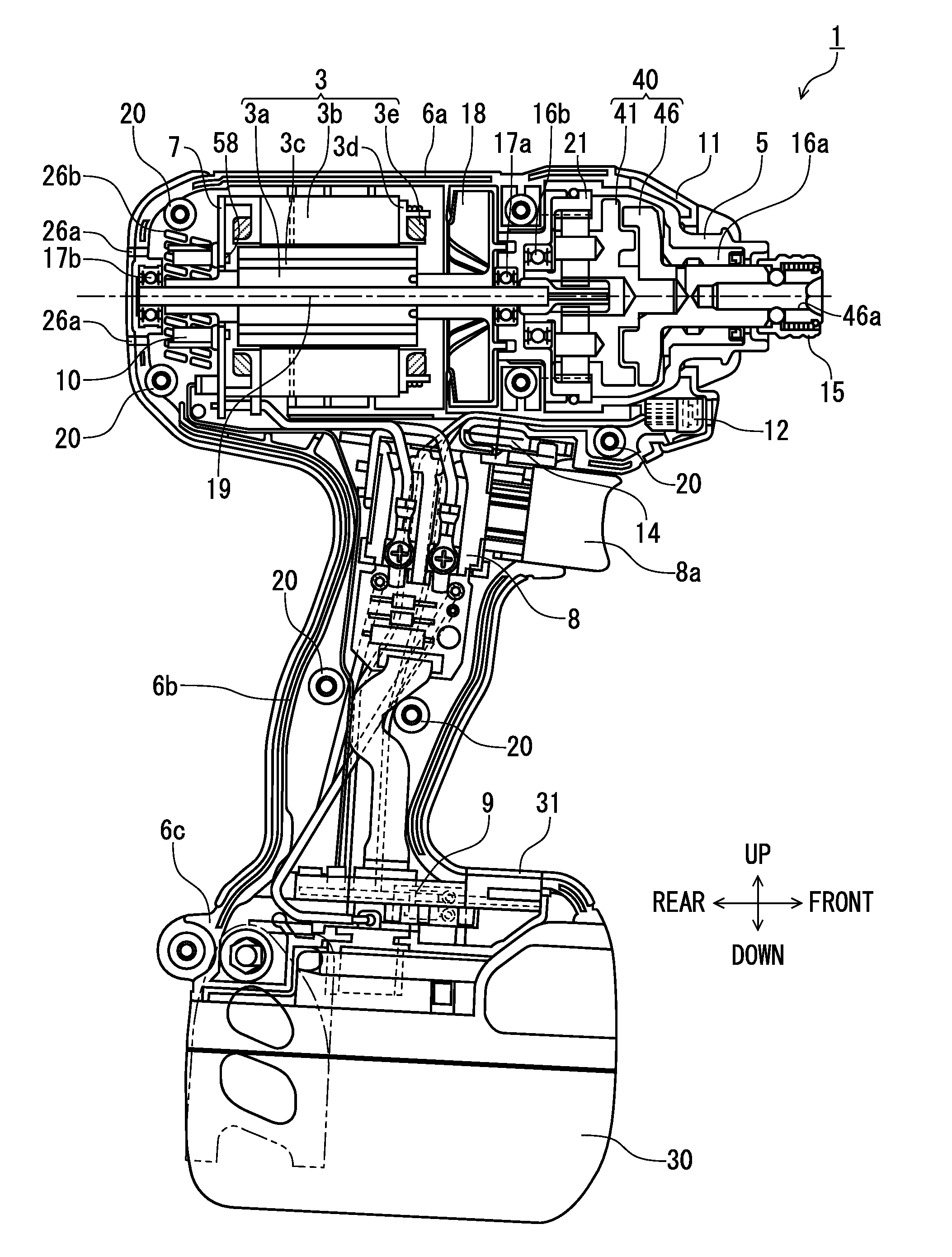
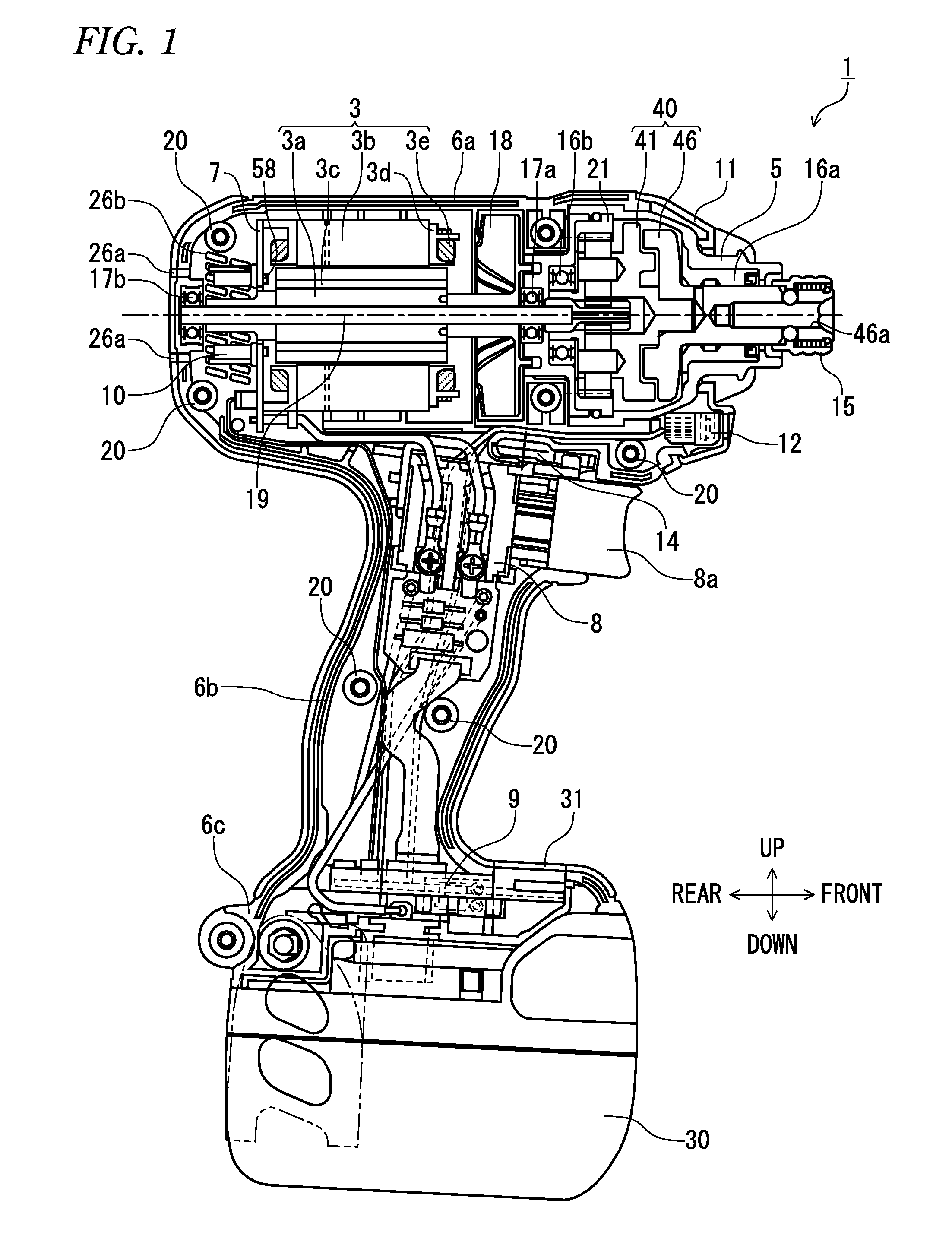
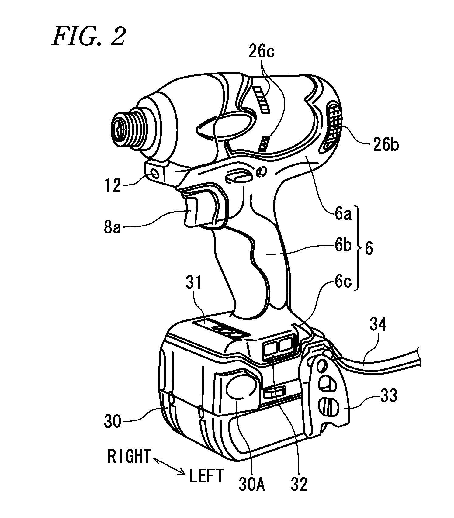
[0035]One object of the invention is to provide an impact tool in which an impact mechanism is realized by a hammer and an anvil with a simple mechanism.

Problems solved by technology

As a result, the number of parts of the spindle and the hammer increases, high attaching accuracy between the spindle and the hammer is required, thereby increasing the manufacturing cost.
Further, even if a drill mode is realized (even if a retreat operation of the hammer is controlled), in order to realize even the clutch operation of interrupting power transmission when a given fastening torque is achieved, it is necessary to provide a clutch mechanism separately, and realizing the drill mode and the drill mode with a clutch in the impact tool leads to cost increase.
As a result, excessive electric power is supplied to the motor, and useless power consumption occurs.
And, a so-called coming-out phenomenon occurs where a screw advances excessively during screwing as striking is performed with a high fastening torque, and the tip tool is separated from a screw head.
However, in a conventional power tool, the engaging projection collides in a state where the speed has been increased by the motor.
For this reason, a problem occurs in that the impact of the collision between the engaging projection and the engaged projection becomes large, and fastening torque increases.
Particularly when the increased fastening of fastening a screw or the like which has been fastened again is performed, since the fastening torque is already imparted to the screw, the torque may become excessively large due to the impact of the collision between the engaging projection and the engaged projection.
However, in the conventional power tool, the operation continues unless the worker takes his / her finger off the trigger.
Therefore, useless power consumption occurs, and the temperature of the motor also rises.
Therefore, the power consumption and the temperature rise of the battery are conspicuous.
However, in the conventional power tool, when a trigger is depressed in a state where the fitting between a screw and a tip tool is in an imperfect state at the time of start-up, the fitting between the screw and the tip tool may be released (coming-out), and the head of the screw may be damaged.
Additionally, if the ambient temperature is high, switching elements for supplying electric power to coils of the motor may be damaged as the switching elements generate heat.
However, in the newly developed electronic pulse driver, the fitting between a screw or the like and a tip tool may be released (come-out), and the head of the screw may be damaged.
Moreover, a force in the direction reverse to the rotational direction is generated in the power tool by the reaction caused by the operation after seating, and the worker experiences discomport.
However, in the conventional power tool, it is difficult to perform fastening according to the fasteners used.
Moreover, when the fastening work of a bolt is performed, further fastening cannot be performed after seating.
Therefore, when the normal rotation time of pulses is long, a force reverse to a rotational direction is generated in an impact driver by the reaction of the bolt, and the worker experiences discomfort.
As such, in the power tool in which generation of heat of the motor becomes large, the temperature of the motor may rise excessively in a case where the motor is controlled regardless of the temperature of the motor.
However, in the newly developed electronic pulse driver, if the normal rotation time is long during high-load work, the reaction of the impact driver also increases, and the worker experiences increasing discomfort.

Method used


Image

  • Impact tool
  • Impact tool
  • Impact tool

Examples


second embodiment

[0206]Next, before the striking operation of the hammer 41 and the anvil 46 related to the present embodiment is described, the basic construction of the hammer and the anvil and the striking operation principle thereof will be described with reference to FIGS. 6 and 7. FIG. 6 illustrates the hammer 151 and the anvil 156 related to a basic construction (a second embodiment). The hammer 151 is formed with a set of protruding portions, i.e., a protruding portion 152 and a protruding portion 153 which protrude axially from the cylindrical main body portion 151b. The front center of the main body portion 151b is formed with a fitting shaft 151a which fits to a fitting groove (not shown) formed at the rear of the anvil 156, and the hammer 151 and the anvil 156 are connected together so as to be rotatable relative to each other by a given angle of less than one rotation (less than 360 degrees). The protruding portion 152 acts as a striking pawl, and has planar striking-side surfaces 152a ...

fourth embodiment

[0333]Next, an electronic pulse driver 1201 will be described with reference to FIGS. 28 and 29.

third embodiment

[0334]In the third embodiment, the aspect of striking has been changed when an electric current or the like has been increased to a certain threshold value, without taking a change in temperature into consideration. However, for example, since the viscosity of the grease within the gear mechanism 1041 is low in cold districts, an electric current which flows into the motor 1003 tends to become greater than usual. In that case, an electric current which flows into the motor 1003 is apt to exceed the threshold value, and irrespective of a situation where the aspect of striking is changed, there is a possibility of changing the striking aspect.

[0335]Accordingly, the present embodiment is characterized by changing a threshold value in consideration of a change in temperature. Specifically, a temperature detection unit is provided on the switching board 1063, and the control unit 1072 changes each threshold value Based on a temperature detected by the temperature detection unit.

[0336]FIG...


PUM

PropertyMeasurementUnit
Timeaaaaaaaaaa
Lengthaaaaaaaaaa
Ratioaaaaaaaaaa

Abstract

According to an aspect of the present invention, there is provided an impact tool including: a motor drivable in an intermittent driving mode; a hammer connected to the motor; an anvil to be struck by the hammer to thereby rotate / strike a tip tool; and a control unit that controls a rotation of the motor by switching a driving pulse supplied to the motor in accordance with a load applied onto the tip tool.

Description

TECHNICAL FIELD[0001]An aspect of the present invention relates to an impact tool which is driven by a motor and realizes a new striking mechanism.[0002]Another aspect of the present invention relates to a power tool, and particularly, to an electronic pulse driver which outputs a rotational driving force.[0003]Still another aspect of the present invention relates to a power tool, and particularly, to an electronic pulse driver which outputs a rotational driving force.[0004]Still another aspect of the present invention relates to a power tool, and particularly, to an electronic pulse driver which outputs a rotational driving force.[0005]Still another aspect of the present invention relates to a power tool, and particularly, to an electronic pulse driver which outputs a rotational driving force.[0006]Still another aspect of the present invention relates to a power tool, and particularly, to an electronic pulse driver which outputs a rotational driving force.[0007]Still another aspect...

Claims


Application Information

Patent Timeline
IPC IPC(8): B25B21/02B25D11/04
CPCB25B21/02B25B23/1475B25B21/026B25B23/147
Inventor TANIMOTO, HIDEYUKITAKANO, NOBUHIRONISHIKAWA, TOMOMASAIWATA, KAZUTAKAMASHIKO, HIRONORIYAMAGUCHI, HAYATONAKAGAWA, ATSUSHIOOMORI, KATSUHIRONAKAMURA, MIZUHOUCHIDA, HIROKINAKANO, SAROMAITO, YUTAKA
Owner HITACHI KOKI CO LTD
Learn More