
Methods of fabricating trench isolation structures having varying depth

a technology of trench isolation and trench structure, which is applied in the direction of solid separation, grading, chemistry apparatus and processes, etc., can solve problems such as forming voids, and achieve the effect of superior isolation ability and high operation voltag

Active Publication Date: 2009-04-21
SAMSUNG ELECTRONICS CO LTD
View PDF21 Cites 6 Cited by
  • Summary
  • Abstract
  • Description
  • Claims
  • Application Information

AI Technical Summary

Benefits of technology

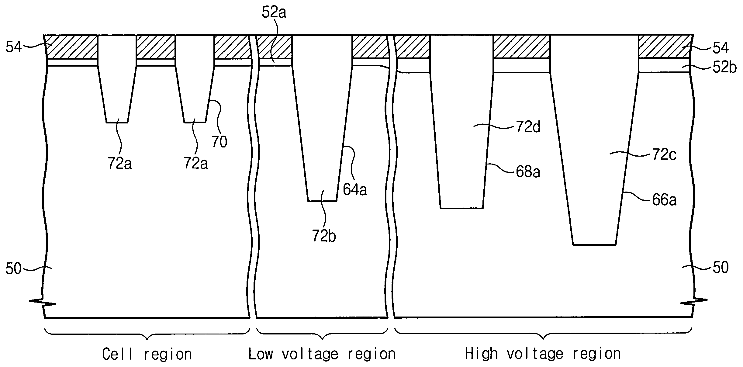
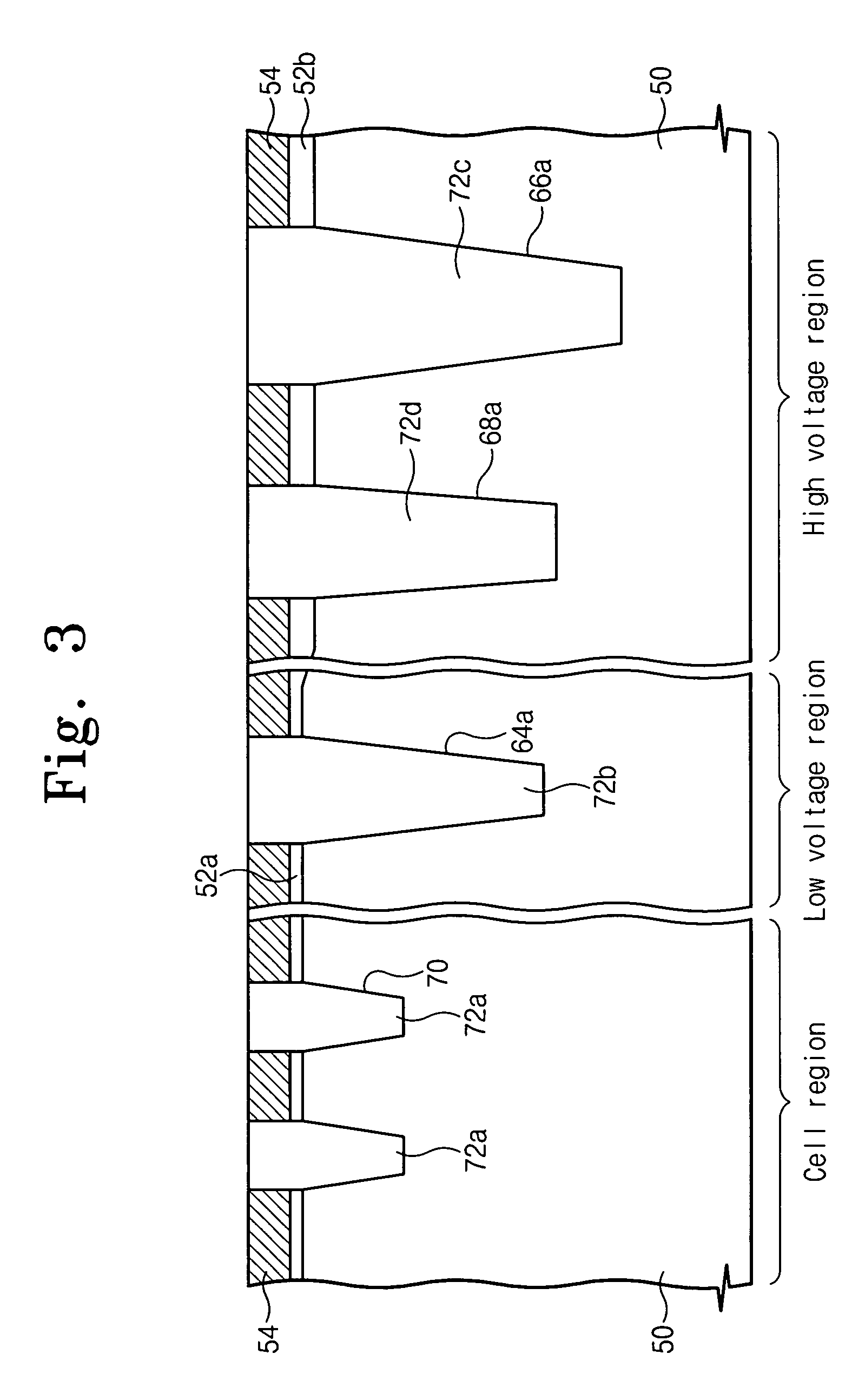
[0017]Some embodiments of the invention may provide a device isolation structure that is sufficiently filled with an insulation layer at a high density pattern region while having superior isolation ability where high operation voltage is supplied.

Problems solved by technology

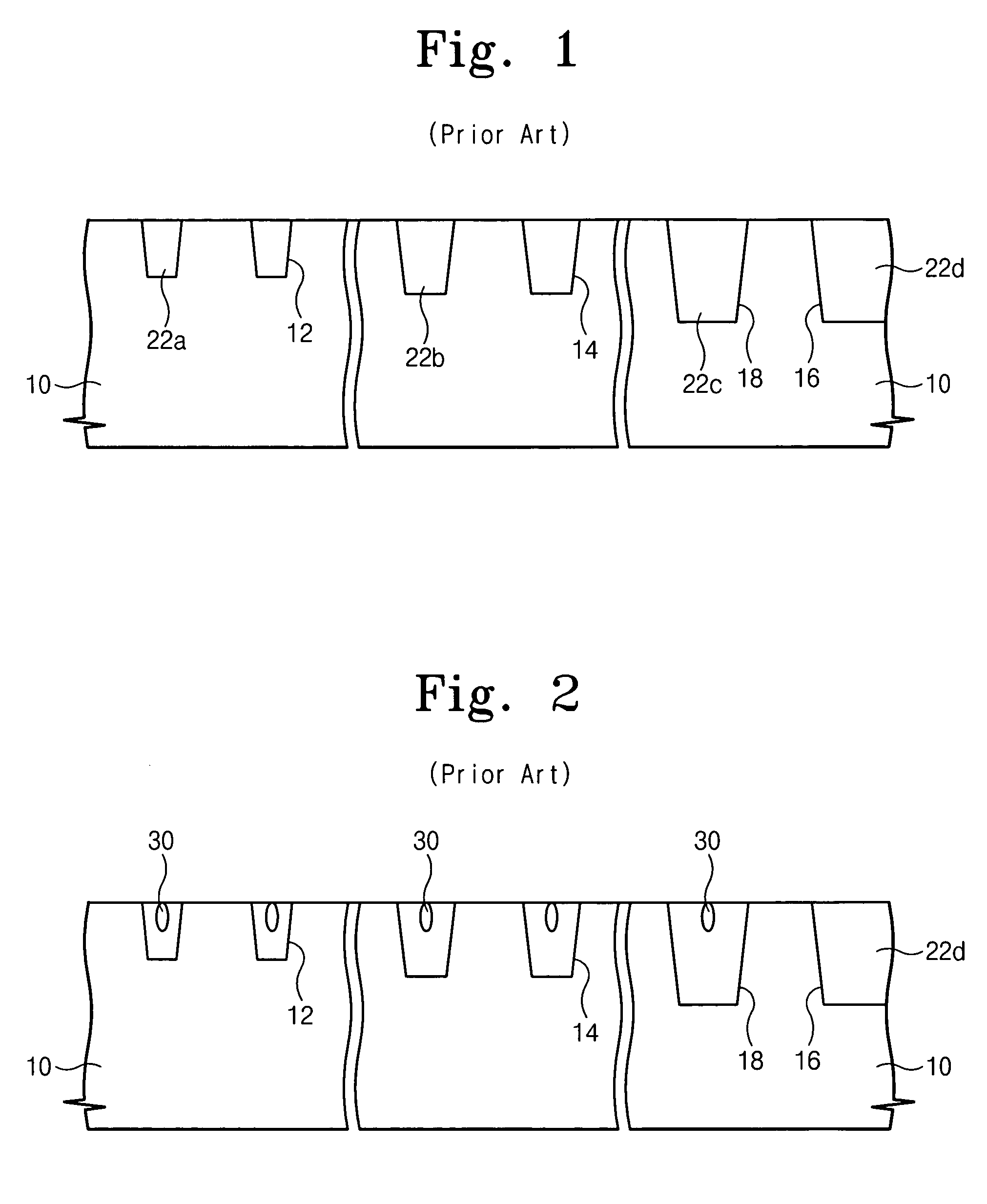
Accordingly, the trenches in the cell region and the low voltage region may not sufficiently fill with insulating material, and may therefore form voids 30.

Method used


Image

  • Methods of fabricating trench isolation structures having varying depth
  • Methods of fabricating trench isolation structures having varying depth
  • Methods of fabricating trench isolation structures having varying depth

Examples


Embodiment Construction

[0029]The present invention will be described more fully hereinafter with reference to the accompanying drawings, in which embodiments of the invention are shown. However, this invention should not be construed as limited to the embodiments set forth herein. Rather, these embodiments are provided so that this disclosure will be thorough and complete, and will fully convey the scope of the invention to those skilled in the art. In the drawings, the thickness of layers and regions are exaggerated for clarity. Like numbers refer to like elements throughout. As used herein the term “and / or” includes any and all combinations of one or more of the associated listed items.

[0030]The terminology used herein is for the purpose of describing particular embodiments and is not intended to be limiting of the invention. As used herein, the singular forms “a”, “an” and“the” are intended to include the plural forms as well, unless the context clearly indicates otherwise. It will be further understoo...


PUM


Abstract

A device isolation structure of semiconductor device includes a semiconductor substrate having a cell region, a low voltage region and a high voltage region defined therein. A cell trench isolation region is disposed in the cell region. A low voltage trench isolation region is disposed in the low voltage region and extends deeper into the substrate than the cell trench isolation region. A first high voltage trench isolation region is disposed in the high voltage region and extends deeper into the substrate than the low voltage trench isolation region. A second high voltage trench isolation region is disposed in the high voltage region and extends deeper into the substrate than the low voltage trench isolation region but shallower than the first high voltage trench isolation region.

Description

CROSS-REFERENCE TO RELATED APPLICATION[0001]This U.S. non-provisional patent application claims priority under 35 U.S.C. § 119 of Korean Patent Application 2005-25984 filed on Mar. 29, 2005, the entire contents of which are hereby incorporated by reference.BACKGROUND OF THE INVENTION[0002]The present invention relates to semiconductor devices and methods of fabricating the same, more particularly, to device isolation structures of semiconductor devices and methods of fabricating the same.[0003]A typical semiconductor integrated circuit device has various components arranged in and / or on a substrate. The components are electrically connected in accordance to perform specific functions. The components are generally electrically isolated except for certain electrical connections. Device isolation structures are used to provide electric isolation between neighboring components.[0004]As the level of integration of semiconductor devices has increased, the size of device isolation structur...

Claims


Application Information

Patent Timeline
Patent Type & Authority Patents(United States)
IPC IPC(8): H01L21/76
CPCH01L21/76229B07B1/28B07B1/42B07B1/4636B07B13/04
Inventor CHOI, EUN-YOUNGSON, JUNG-MIN
Owner SAMSUNG ELECTRONICS CO LTD
Learn More