
Subsea separation apparatus for treating crude oil comprising a separator module with a separator tank

a separation apparatus and separator tank technology, applied in the direction of separation process, water cleaning, borehole/well accessories, etc., can solve the problems of imposing limitations on the weight and other design parameters of such plants, requiring a lot of additional equipment, and placing such separation equipment on offshore platforms. , to achieve the effect of preventing the retrieval of installed equipment to the surface, and reducing the retension tim

Inactive Publication Date: 2009-04-21
VETCO GRAY SCANDINAVIA +1
View PDF8 Cites 30 Cited by
  • Summary
  • Abstract
  • Description
  • Claims
  • Application Information

AI Technical Summary

Benefits of technology

The present invention is about a method and apparatus for separating crude oil from water, gas, sand, and other fluids in a subsea separation plant. The invention involves a separator tank that is designed to have a greater pressure resistance towards internal pressure than towards external pressure, so that loss of internal pressure will not result in a collapse. The tank is placed on the seabed, directly on the well head, and is designed to be easily assembled and maintained. The invention also includes a protective structure for the tank, a pump for process water injection, and a control system for the plant. The invention allows for the separation of water from the crude oil, with the water being directly reinjected into the well bore. The plant can be connected to a well head with a production well or a multiple tubing completion. The plant can be placed on a temporary or permanent basis and is designed to be easily assembled and maintained. The invention also includes a module system for the plant, with various elements placed on the seabed and connected together. The plant can be connected to a well head with a production well or a multiple tubing completion. The invention is environmentally friendly and cost-effective.

Problems solved by technology

However, there are disadvantages connected to placing such separation equipment on offshore platforms.
In many cases, the platforms impose limitations upon the weight and other design parameters of such plants.
In addition, any reinjection of water into the well will require a lot of additional equipment for leading separated water down into the well.
Alternatively, cleaned, but still oil containing water may be dumped directly into the sea, but this is problematic in areas sensitive to pollution.
The solution primarily concerns an arrangement and a method for sand processing, and appears limited to the separation of sand in produced water.
The disadvantage of this is that the pump must circulate sand containing water, which involves a considerable risk for increased wear with correspondingly high maintenance frequency.
This is very cost intensive.
The handling of sand production is a common problem for underwater separation plants.

Method used


Image

  • Subsea separation apparatus for treating crude oil comprising a separator module with a separator tank
  • Subsea separation apparatus for treating crude oil comprising a separator module with a separator tank
  • Subsea separation apparatus for treating crude oil comprising a separator module with a separator tank

Examples


Embodiment Construction

[0058]The invention will now be described in greater detail with reference to the enclosed drawings, where similar reference numerals refer to similar components.

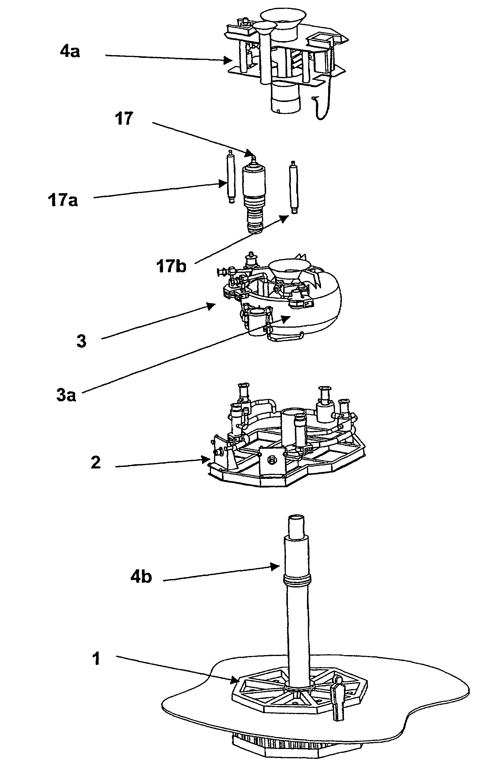
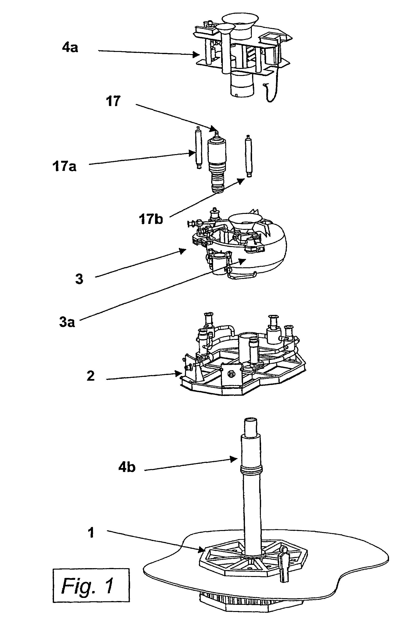
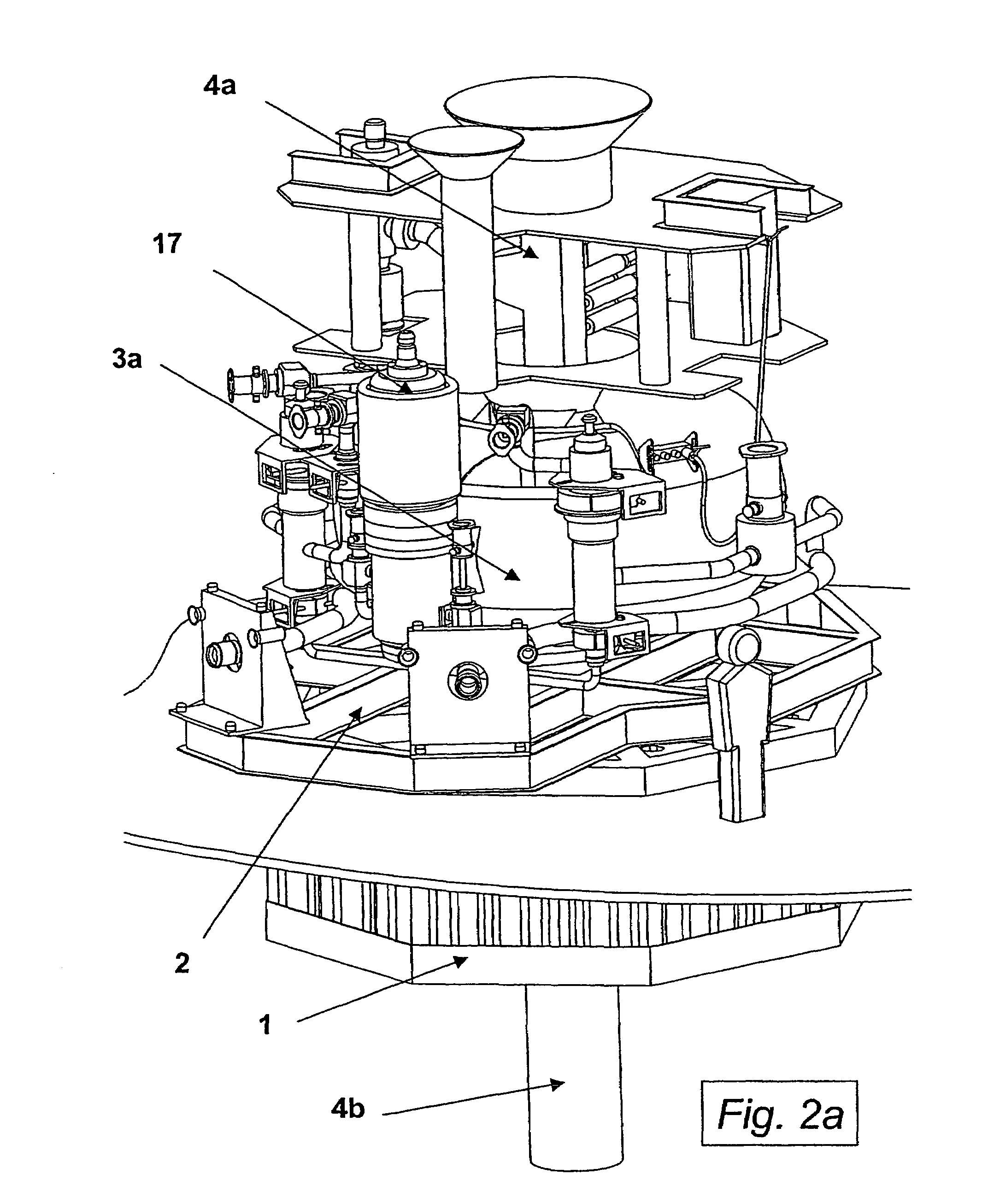
[0059]FIG. 1 is an example of a separation plant with a separator module 3 according to the invention, on a well head. The separation plant is shown with a valve tree or water injection tree 4a (shown as a guidelineless type) for the injection of separated water. The water injection tree 4a has inserts such as a hydrocyclone for gas / liquid and / or particle separation 17a, a hydrocyclone for oil separation and / or sand mixer 17b, a booster pump 17 for separated water, a manifold and guide frame for any guidelines or pillars called guide base or flow base 2 (PGB), a well head completion 4b, and a base frame 1 (TGB). The retrievable inserts (not shown on FIG. 1) may include sand cyclone modules, connection spools 6, water injection pumps, transformer modules, a ROV winch, control parts, a choke bridge module, a connecting point ...


PUM

PropertyMeasurementUnit
gravityaaaaaaaaaa
heightaaaaaaaaaa
pressureaaaaaaaaaa

Abstract

A subsea separation apparatus for processing crude oil, which includes a separator module with a separator tank. The separator tank defines an opening going there through. The opening is located substantially at the geometrical center of the separator tank, and may be used for other processing equipment for the crude oil. The separator tank may be substantially symmetrically placed on a well head, and the separator module may be substantially concentrically placed on the well head.

Description

BACKGROUND OF THE INVENTION[0001]1. Field of the Invention[0002]The present invention concerns a subsea separation apparatus for treating crude oil comprising a separator module with a separator tank for the separation of water, gas, sand and crude oil from fluids flowing from a well. The apparatus or plant is designed to be placed on the seabed adjacent to, or on the well.[0003]2. Description of Related Art[0004]During the exploitation of oil and gas offshore, the produced fluids are usually led to a plant, for instance on an offshore platform, for the separation of the various phases of the fluid. These phases mainly include hydrocarbons, water, and in some cases, sand. The separation is usually performed with conventional separation equipment such as hydrocyclones and sedimentation tanks.[0005]However, there are disadvantages connected to placing such separation equipment on offshore platforms. In many cases, the platforms impose limitations upon the weight and other design param...

Claims


Application Information

Patent Timeline
Patent Type & Authority Patents(United States)
IPC IPC(8): E21B43/00B01D17/00E21B43/36E21B43/40
CPCB01D17/00E21B43/36E21B43/40B01D17/0208B01D17/0211B01D17/0214B01D17/0217
Inventor OSTERGAARD, INGE
Owner VETCO GRAY SCANDINAVIA
Learn More