
Side-release buckle assembly

a buckle and side release technology, applied in the direction of fastenings, garment fasteners, press-button fasteners, etc., can solve the problems of difficult or impossible connection, rendering full and proper mating with the male connection member b>12 difficult or impossible, and reducing the service life of the male connection member b>12/b>, so as to achieve convenient connection and disconnect.

Inactive Publication Date: 2008-04-17
ILLINOIS TOOL WORKS INC
View PDF6 Cites 14 Cited by
  • Summary
  • Abstract
  • Description
  • Claims
  • Application Information

AI Technical Summary

Benefits of technology

[0011]Embodiments of the present invention provide a robust buckle assembly having mating components that are easily connected and disconnected when desired. Additionally, embodiments of the present invention are less susceptible to being clogged with snow or debris as compared to conventional buckle assemblies.
[0016]One or both of the buckle connectors include a main body connected to a strap beam. The strap beam may be recessed with respect to the main body in order to facilitate easy strap / web adjustment, and to provide a clear area for foreign substances to exit from the passage.

Problems solved by technology

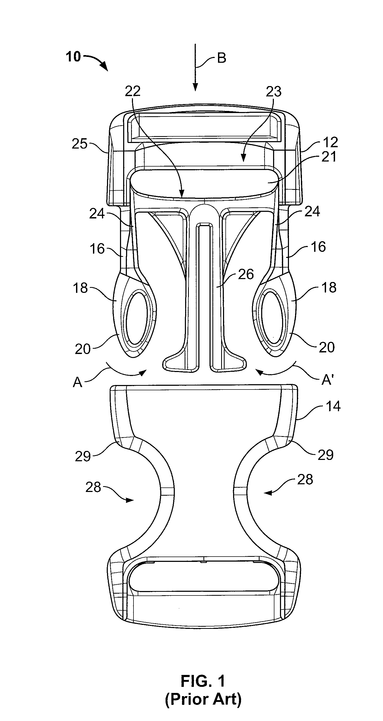
As such, an operator may find it difficult, or impossible, to disconnect the male connection member 12 from the female connection member 14.
In snowy conditions, however, some conventional buckle assemblies, such as the buckle assembly 10, may become clogged with snow, rendering connection difficult.
That is, snow or other debris may become trapped within the female connection member 14, thereby rendering full and proper mating with the male connection member 12 difficult or impossible.
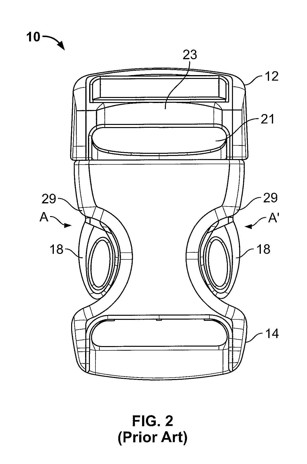
Additionally, the webbing adjustment areas of the conventional buckle assembly 10 are not always easily accessible because the main bodies of the male and female connection members 12 and 14 may interfere with an operator's fingers and / or the strap / web material during adjustment.
Thus, an operator may find it difficult to adjust webbing or straps positioned within the strap receiving channels of the male and female connection members 12 and 14.

Method used


Image

  • Side-release buckle assembly
  • Side-release buckle assembly
  • Side-release buckle assembly

Examples


Embodiment Construction

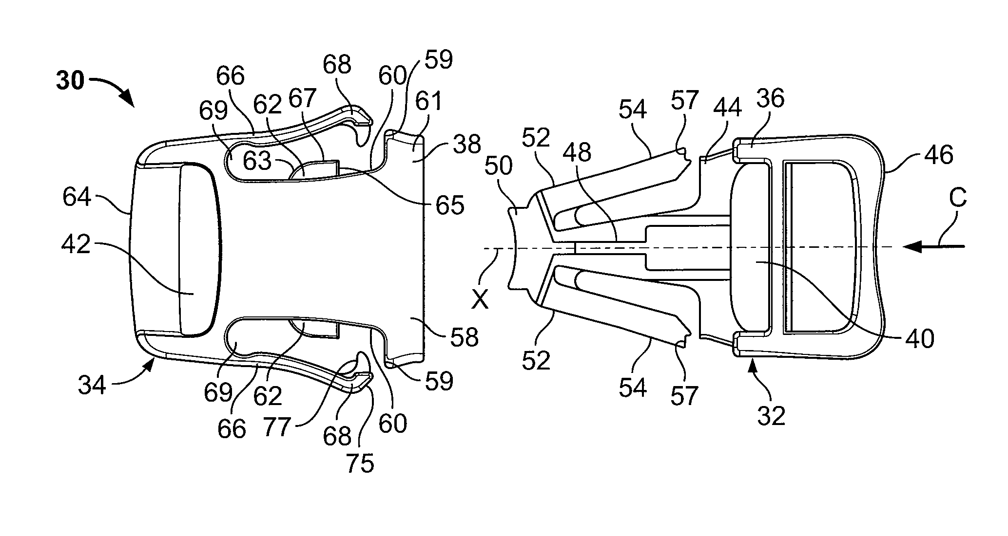
[0028]FIGS. 3 and 4 illustrate top and bottom views, respectively, of a disconnected buckle assembly 30 according to an embodiment of the present invention. The buckle assembly 30 includes a male connection member 32, or male buckle connector, that is configured to mate with a female connection member 34, or female buckle connector. Both the male and female connection members32 and 34 include main bodies 36 and 38, respectively, that include strap channels 40 and 42, respectively, one or both of which may be configured to slidably retain a strap therein.

[0029]The main body 36 of the male connection member 32 includes a rigid cross beam 44 integrally connected to a strap beam 46. The strap channel 40 is formed between the cross beam 44 and the strap beam 46. An extension beam 48 outwardly extends from the cross beam 44, and may be formed perpendicular with respect to the cross beam 44. As shown in FIGS. 3 and 4, for example, the extension beam 48 may be aligned with and located about...


PUM


Abstract

A buckle assembly includes a first connection member and a second connection member. The first connection member includes engagement members, such as buttons. The second connection member is configured to connect to the first connection member, and includes openings in which the engagement members are retained when the first connection member is connected to the second connection member. The second connection member also includes release arms configured to be actuated to engage the engagement members in order to disconnect the first connection member from the second connection member.

Description

RELATED APPLICATIONS[0001]This application relates to and claims priority benefits from U.S. Provisional Patent Application 60 / 851,199 entitled “Buckle Assembly,” filed Oct. 12, 2006, which is hereby incorporated by reference in its entirety.FIELD OF THE INVENTION[0002]Embodiments of the present invention generally relate to a buckle assembly, and more particularly to a side-release buckle assembly.BACKGROUND OF THE INVENTION[0003]A conventional side-release buckle assembly includes a male connection member that is configured to mate with a female connection member, such as shown and described in U.S. Pat. No. 5,465,472, entitled “Buckle.” Each connection member is configured to retain a strap, such as a seatbelt or backpack strap. The male connection member includes integral buttons that may be engaged to release the male connection member from the female connection member, thereby disconnecting the buckle assembly.[0004]FIG. 1 illustrates a top view of a disconnected conventional ...

Claims


Application Information

Patent Timeline
IPC IPC(8): A44B11/25A44B11/00A44B11/22
CPCA44B11/266Y10T24/45785Y10T24/45534Y10T24/45581
Inventor KOLASA, SCOTT D.
Owner ILLINOIS TOOL WORKS INC
Learn More