Transparent window with non-transparent contact surface for a soldering bonding

Active Publication Date: 2009-04-21
SAINT-GOBAIN GLASS FRANCE
View PDF20 Cites 7 Cited by
  • Summary
  • Abstract
  • Description
  • Claims
  • Application Information

AI Technical Summary

Benefits of technology

[0014]If the contact surface is applied by screen printing, it will be advantageous to provide, in the screen-printing screen, at the place of the location or locations in question, an appropriate mask that prevents application of the screen-printing paste in the region of the cutout. If the contact surface is formed by a band of metal foil, the cutout may be cut out or stamped by suitable tools at the intended point.
[0018]As another advantage of said cutout or cutouts in the soldering region of the contact surface, it has been found that a higher mechanical strength is also provided at the location of the actual soldering, in such a way that the connection piece can withstand higher tensile forces. This is an advantage when continuing to handle such a pane, while it is being transported and fitted, because it is rare for connection pieces to be soldered, that have been inadvertently broken, to be able to be repaired or, depending on the case, the pane in question must be extracted from the series.

Problems solved by technology

In general, for transparent panes provided with contact surfaces, in particular for the soldering places located on the inside of a composite glazing panel, which are heated only after this composite has been manufactured, the problem arises of being able to reliably check the result of the soldering through the pane.

Method used


Image

  • Transparent window with non-transparent contact surface for a soldering bonding
  • Transparent window with non-transparent contact surface for a soldering bonding

Examples


Embodiment Construction

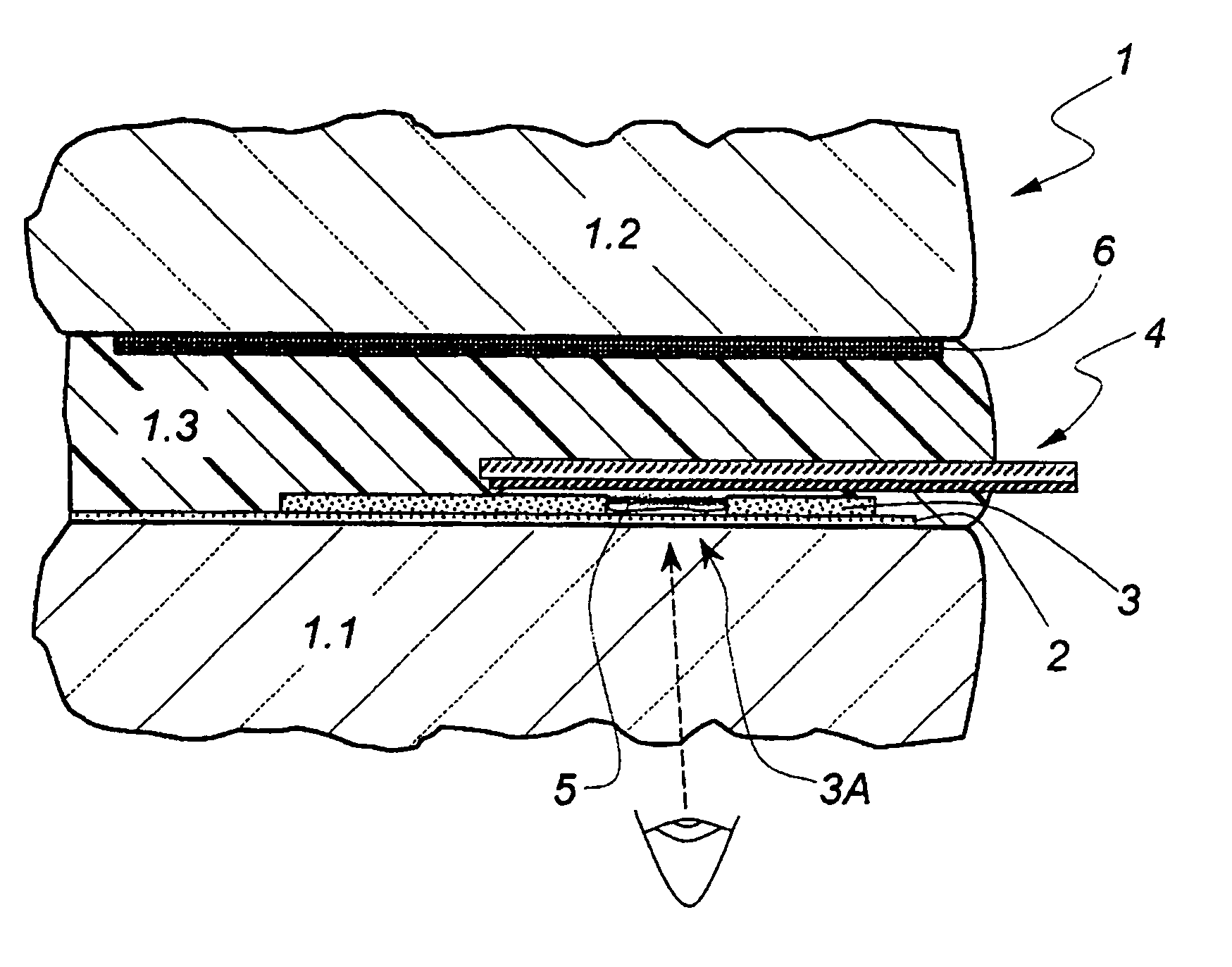
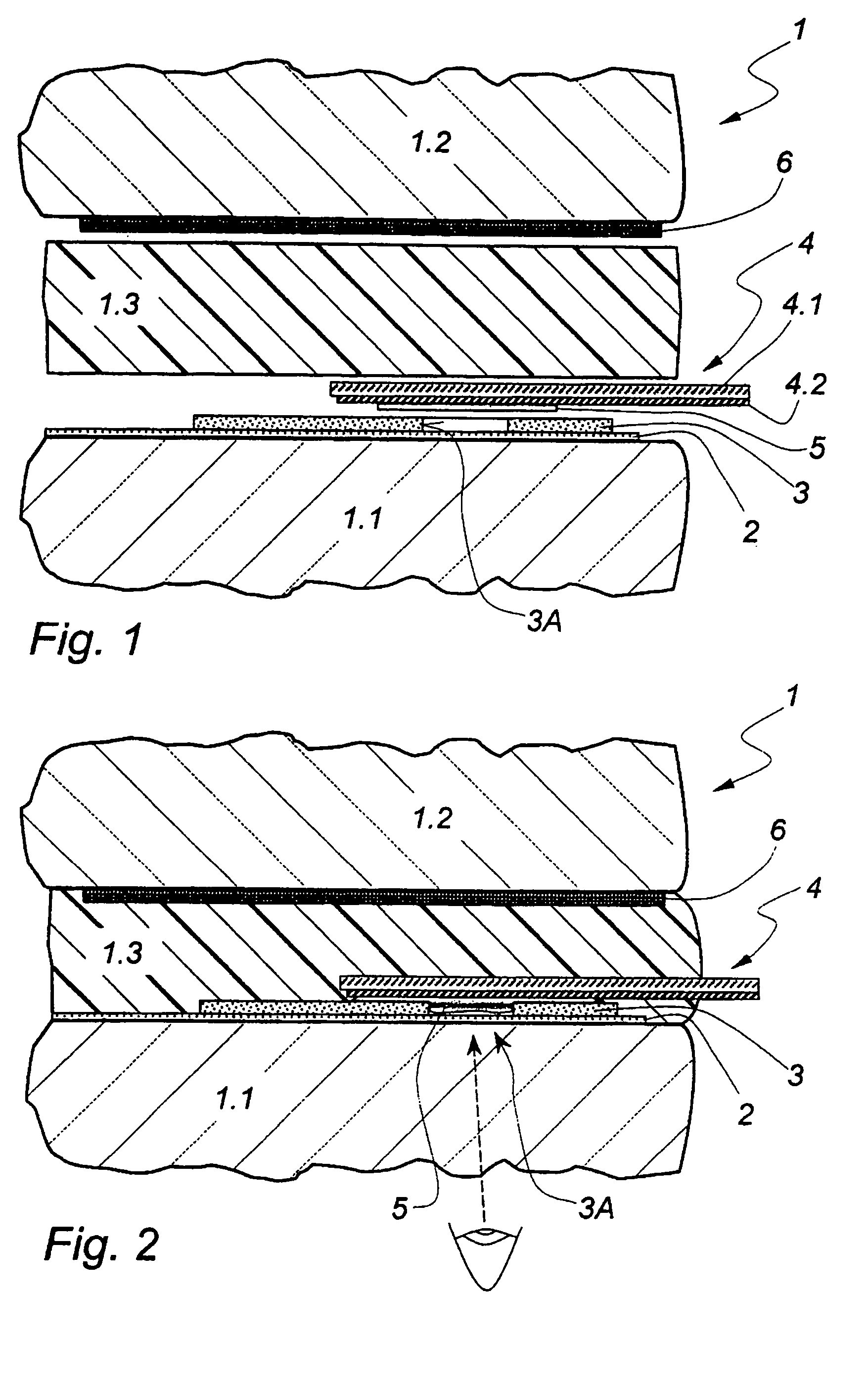
[0025]FIG. 1 shows an exploded representation of the border region of a composite glazing panel 1, essentially formed from a first rigid pane 1.1, a second rigid pane 1.2 and a thermoplastic and adhesive interlayer 1.3. The two rigid panes are preferably made of glass, but they may, however, also be made of synthetic material. The interlayer is, for example, a sheet of polyvinyl butyral—the usual adhesive material for composite glazing panels.

[0026]A thin-film system 2, highly transparent for visible light and capable of being thermally stressed, is applied to that plane surface of the rigid pane 1.1 which faces the interlayer. It comprises at least one electrically conducting functional layer, preferably made of metal, and antireflection layers that contain, between them, said functional layer. The more detailed structure of the multilayer system is not essential as regards the invention in question here, so that it will not be explained further.

[0027]Moreover, in addition to its t...


PUM

PropertyMeasurementUnit
Transparencyaaaaaaaaaa

Abstract

A transparent pane, in particular a glass pane, having at least one electroconducting, non-transparent contact surface placed on one of its surfaces, to connect it by soldering to a connection piece. In the region of the soldering location, the contact surface has at least one cutout via which the soldering filler metal is visible through the pane after the connection piece has been soldered to the contact surface. Such a configuration allows reliable visual verification of the soldering locations, even in cases in which the soldering location is incorporated within a composite glazing panel and has been soldered, if necessary by induction heating.

Description

BACKGROUND OF THE INVENTION[0001]1. Field of the Invention[0002]The invention relates to a transparent pane, in particular a glass pane, having at least one electroconducting, nontransparent contact surface placed on one of its surfaces, in order to connect it by soldering to a connection piece.[0003]2. Description of Related Art[0004]Such panes are known in many constructions. In most applications, the panes carry, on their surface, electrical functional elements such as electrically conducting tracks, heating surfaces, or antennas, again in the form of coatings over the entire surface, which have to be connected with at least one contact surface to an external connection piece by soldering.[0005]Often the contact surfaces (for example, the conducting tracks or, depending on the case, the functional elements themselves) are produced by applying an electrically conducting paste to be baked; sometimes, thin strips of tinned metal foil are also used, these being connected by soldering...

Claims


Application Information

Patent Timeline
IPC IPC(8): B23K31/02H05B3/16B23K1/00B32B17/10H01R4/02H05B3/84H05K1/02H05K1/11H05K3/36
CPCB23K1/0008B32B17/10036B32B17/10174B32B17/10761H01R4/02H05B3/84H05K3/363H01R2201/26H05B2203/016H05K1/0269H05K1/111H05K2201/0108H05K2201/0326H05K2201/0969H05B3/86
Inventor CRUMBACH, RICHARDREUL, BERNHARDSZNERSKI, ANDREAS
Owner SAINT-GOBAIN GLASS FRANCE
Why Eureka
Try Eureka