
Hybrid power-generating device

a power-generating device and hybrid technology, applied in the direction of motors, wind energy generation, electrical apparatus, etc., to achieve the effects of reducing operating costs, enhancing the driving effect of apparatuses, and improving stability of power grids

Active Publication Date: 2009-04-14
IND TECH RES INST
View PDF28 Cites 32 Cited by
  • Summary
  • Abstract
  • Description
  • Claims
  • Application Information

AI Technical Summary

Benefits of technology

[0020]In view of the descriptions of prior art, the primary object of the present invention is to provide a hybrid power-generating device, being provided with the benefits of two different types of electrical generators as the two are complementary to each other. In a preferred embodiment, the hybrid power-generating device integrates a doubly-fed induction generator (DFIG) and a synchronous generator (SG) while using the DFIG as its primary electrical generator and the SG as its auxiliary electrical generator as the rated power of the SG is specified to be no larger than one third of the DFIG, by which not only the overall performance of the hybrid power-generating device as well as the apparatus driven thereby are enhanced and the stability of power grid are improved, but also the operating cost thereof is reduced.
[0021]It is another object of the invention is to provide a hybrid power-generating device having a structure integrating a doubly-fed induction generator (DFIG) and a synchronous generator (SG) and a power generating method thereof, by which the characteristic of the SG that is not defined by a rotation speed range of ±30% is utilized for enabling the hybrid power-generating device to generate electricity even at a low wind speed that is not within the speed range specified by the DFIG to generate electricity. In other words, the cut-in speed of the wind power generating device (wind turbine) can be reduced for improving its annual energy production and thus the average energy production cost is reduced.
[0022]Yet, another object of the invention is to provide a hybrid power-generating device having a structure integrating a doubly-fed induction generator (DFIG) and a synchronous generator (SG) and a power generating method thereof, by which when the power converter connected to the rotors of the DFIG is exceeding its safety specification and being disabled as the electrical grid connecting to the hybrid power-generating device is subjecting to a sudden voltage dip, that is, when the DFIG is off grid and the grid can not be used for maintaining the DC bus voltage, the power converter of the SG is activated for maintaining the DC bus voltage and thus the hybrid power-generating device is able to keep generating reactive power for assisting the voltage recovery during the faulted condition.

Problems solved by technology

However, for most of the time it can not obtain the optimal efficiency on wind energy conversion and has a transmission system that is easily to be affected by gusty wind, moreover, it requires a set of external capacitors to provide the reactive power for supporting the grid voltage.
However power converters are required for enabling variable speed control and thus they are comparatively more expensive.
In addition, in consideration of magnetizing current, a multi-pole structure is not suitable for the induction generators and thus it is necessary to pair the induction generator with a gearbox so that the shaft speed can be compatible with the synchronous speed of the induction generator.
However for the large sized wind turbines, since most PMSGs are custom-made and each requires to be paired with a full power converter, it is still very expensive.
(1) Since it requires a gearbox for speed increasing and its rotor needs to be configured with slip rings, regular maintenance is necessitated.(2) As its practical slip is in the range of ±30%, the cut-in speed of a wind-turbine applying the same is limited by its positive maximum slip.(3) As it adopts a partial power converter and its stators is connected to an electrical grid that causes the decoupling from the electrical grid to be impossible when the wind power generating device (wind turbine) is operating, the wind power generating device (wind turbine) can not maintain it normal operation when the electrical gird is subjected to a sudden voltage dip.
Hence, it is difficult to abide by the transmission system operator's request to maintain the wind power generating device (wind turbine) on the grid and output the reactive power for assisting the voltage recovery during a faulted condition.(4) As the magnetizing current required thereby is supplied by the grid, it is not a stand along device that can operate independently at a remote area, such as an isolated island.
However, as the gearless design will cause a larger torque on the generator that its diameter is comparatively larger, a high power synchronous generator is bulky and thus not easy for transportation and installation.(2) As it is supported by a full power converter and its rotation speed can be controlled more widely, the wind power generating device (wind turbine) using the same can feature a lower cut-in speed.(3) As it is supported by a full power converter so that the wind power generating device (wind turbine) using the same can be decoupled from the electrical grid connected thereto, the wind power generating device (wind turbine) is capable of maintaining its normal operation even when the electrical grid is suffering a sudden voltage dip.
However, comparing to DFIG, the SG is more expensive and bulky.
Currently, most wind power generating devices (wind turbines) only utilize a single generator, thus the performance of the wind power generating device (wind turbine) is restricted by the characteristics of that single generator as stated above and can not be improved by integrating such generator with advantageous characteristics of other generators.
Nevertheless, those plural electrical generators used in the wind power generating device (wind turbine) are still of the same operation principle, so that the performance of the wind power generating device (wind turbine) is still restricted by the characteristics of that particular type of generator.
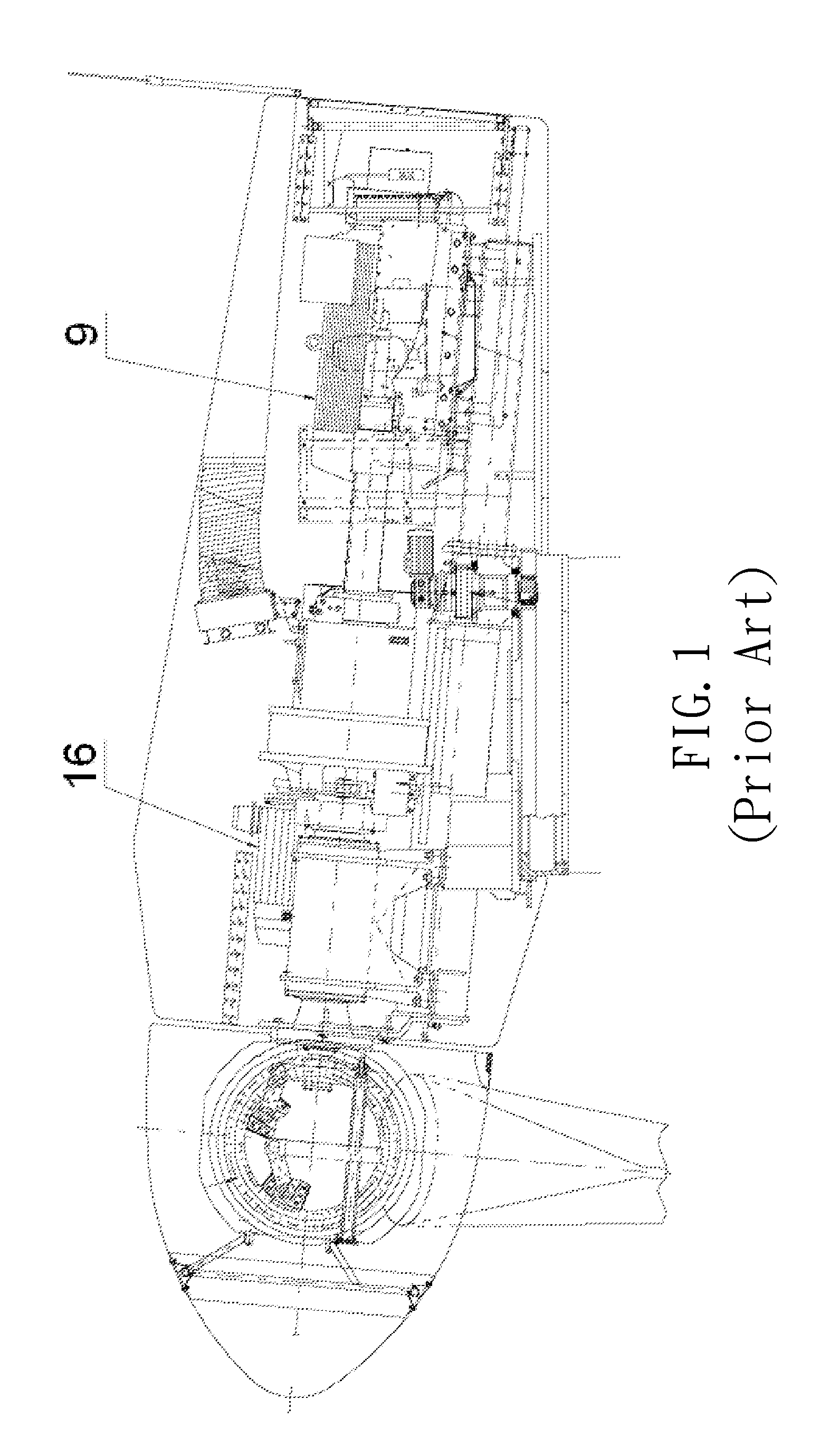
Nevertheless, since the auxiliary wind turbine (unit 2) is acting just as a backup wind turbine, so that the two wind turbines (units 1 and 2) are not being enabled simultaneously for boosting the performance of the wind power generating facility.

Method used


Image

  • Hybrid power-generating device
  • Hybrid power-generating device
  • Hybrid power-generating device

Examples


Embodiment Construction

[0036]For your esteemed members of reviewing committee to further understand and recognize the fulfilled functions and structural characteristics of the invention, several preferable embodiments cooperating with detailed description are presented as the follows.

[0037]Please refer to FIG. 6, which shows a hybrid power-generating device 10 with a hybrid power generator 20 according to a preferred embodiment of the invention. The hybrid power generator 20, being driven by a prime mover, is comprised of a primary electrical generator 21 and an auxiliary electrical generator 22, in which the auxiliary electrical generator 22 is coupled to the primary electrical generator 21 while rendering the rated power of the auxiliary electrical generator 22 to be smaller than that of the primary electrical generator 21. As seen in FIG. 6, the prime mover is an impeller or rotor 30 having a plurality of blades 31, in which the plural blades 31 is electrically connected to a pitch drive system, used f...


PUM


Abstract

The present invention relates to a hybrid power-generating device and a power generating method thereof. The hybrid power-generating device is primarily comprised of: a primary electrical generator and an auxiliary electrical generator with different characteristics, both mechanically coupled to a prime while enabling the rated power of the auxiliary electrical generator to be smaller than that of the primary electrical generator; wherein, as the prime is operating at a low rotation speed or at its initial operating stage, the auxiliary electrical generator is enabled to be driven and activated thereby; and as the operating speed of the driver is stabilized and reaches a predetermined value, the primary electrical generator is then being driven and activated thereby. By the aforesaid hybrid power-generating device, not only the overall performance and the stability of power grid are enhanced, but also the operating cost is reduced.

Description

FIELD OF THE INVENTION[0001]The present invention relates to a hybrid power-generating device and a power generating method thereof, and more particularly, to a hybrid power-generating device, being provided with the benefits of a doubly-fed induction generator (DFIG) and a synchronous generator (SG) while using the DFIG as its primary electrical generator and the SG as its auxiliary electrical generator by specifying the rated power of the SG to be no larger than one third of the DFIG, by which not only the overall performance and the stability of power grid are enhanced, but also the operating cost is reduced for adapting the same to be used in various relating fields.BACKGROUND OF THE INVENTION[0002]Balancing between environment conservation and economic development, the renewable energy conversion device that harnesses natural phenomena, such as wind power, hydro power and solar power, etc., for generating electricity is becoming a focal point of any economy whose every fiber vi...

Claims


Application Information

Patent Timeline
Patent Type & Authority Patents(United States)
IPC IPC(8): H02P9/00
CPCF03D9/002F03D9/003Y02E10/725F03D9/25F03D9/255F03D15/10Y02E10/72
Inventor GUEY, ZEN-JEYCHANG, YUN-YUANWU, CHING-HUEI
Owner IND TECH RES INST
Learn More