
Femtosecond laser apparatus using laser diode optical pumping module

a laser apparatus and optical pumping technology, applied in the direction of lasers, optical resonator shape and construction, semiconductor lasers, etc., can solve the problems of degrading laser power stability, affecting the quality of laser-processing products using characteristics, and inevitably affecting local temperature changes, so as to improve power stability and beam stability

Active Publication Date: 2013-02-28
KOREA ELECTROTECH RES INST
View PDF3 Cites 10 Cited by
  • Summary
  • Abstract
  • Description
  • Claims
  • Application Information

AI Technical Summary

Benefits of technology

The present invention provides an apparatus for stable mode locking in an ultrafast laser, improving power stability and beam stability. The apparatus uses low thermal expansion coefficients to mechanically engage the optical mounts of the diode pumping unit and form a pumping module that is maximally separated from the laser platform or case. This minimizes contact between the module and the laser platform or case, reducing delivery of external thermal deformation to the module. Additionally, mode coupling between the pumping light source and the laser resonator mode is stably maintained, improving the power and beam stability of the laser.

Problems solved by technology

However, a local temperature change inevitably occurs around optical mounts such as an optical pumping-related mount, a laser medium mount, etc., to which a high-power pumping light source is applied, or around a laser power device, a cooling device, etc., which emit much heat to outside due to a cooling pan thereof.
For example, with poor pointing stability of the pumping light source, a spot position of the pumping light source focused strongly with a magnitude of several tens through several hundreds of micrometers in the Ti-Sapphire laser crystal changes inconstantly, such that mode coupling between the pumping light source and the laser beam continuously changes, degrading the laser power stability.
For instance, if characteristics such as output power, output beam direction, and so forth are deteriorated, the quality of a laser-processing product using the characteristics becomes also deteriorated.
However, when optical parts are simultaneously controlled to optimize stability, a system becomes large in size and complex in construction and the price of the system also increases.
When a femtosecond pulse is first generated in mode locking in a femtosecond oscillator, the energy of the pulse is very low of about nano Jule (nJ), and thus the pulse is not suitable for applications such as laser processing and the like.
However, for example, it can be often seen that, if the laser is operated and used, and after being powered-off, the laser is powered on again for operation on the next day, then the characteristics of the laser are deteriorated.
This is because mechanical deformation occurring during power-off is not completely restored by the cooling device even after power-on.
However, it is not easy to maintain optical mounts of a laser resonator at a constant temperature.
If the pumping light source applied from outside is far from the laser crystal, it is not easy to stably maintain the mode coupling due to the beam stability of the pumping light source.
The delivered heat causes mechanical deformation of an optical mount or the like, and the mechanical deformation minutely changes the direction of an optical part, such that the arrangement of the laser resonator is disturbed, degrading the output characteristics of the laser.
In particular, in the ultrafast laser such as the femtosecond laser, a mode locking phenomenon is used to generate a femtosecond pulse, and since mode locking is very sensitive to deformation of the resonator, the stability of the femtosecond pulse is degraded, and finally, mode locking is not maintained any more, such that the femtosecond pulse may not be even generated any more.
Then, as the high-power pumping beam is absorbed in some optical mounts, thermal distribution in the laser becomes non-uniform, resulting in local heating, such that the respective mounts are independently deformed and thus, the arrangement of the resonator of the laser becomes poor.
However, if the laser is powered on again, thermal imbalance occurs again, causing mechanical deformation.
However, since the laser does not completely return to the previous state, mode locking is often broken.

Method used


Image

  • Femtosecond laser apparatus using laser diode optical pumping module
  • Femtosecond laser apparatus using laser diode optical pumping module
  • Femtosecond laser apparatus using laser diode optical pumping module

Examples


Embodiment Construction

[0098]Hereinafter reference will now be made in detail to an embodiment of the present invention, examples of which are illustrated in the accompanying drawings and described below. While the invention will be described in conjunction with the exemplary embodiment, it will be understood that present description is not intended to limit the invention to the exemplary embodiment. On the contrary, the invention is intended to cover not only the exemplary embodiment, but also various alternatives, modifications, equivalents and other embodiments, which may be included within the spirit and scope of the invention as defined by the appended claims.

[0099]Hereinafter, the present invention will be described in detail with reference to the accompanying drawings.

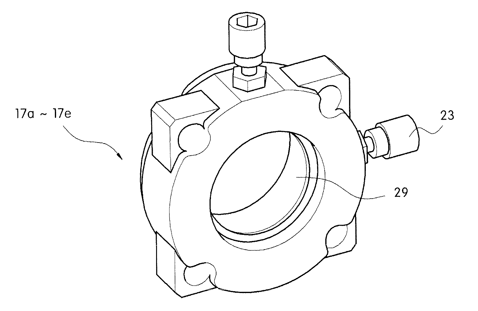
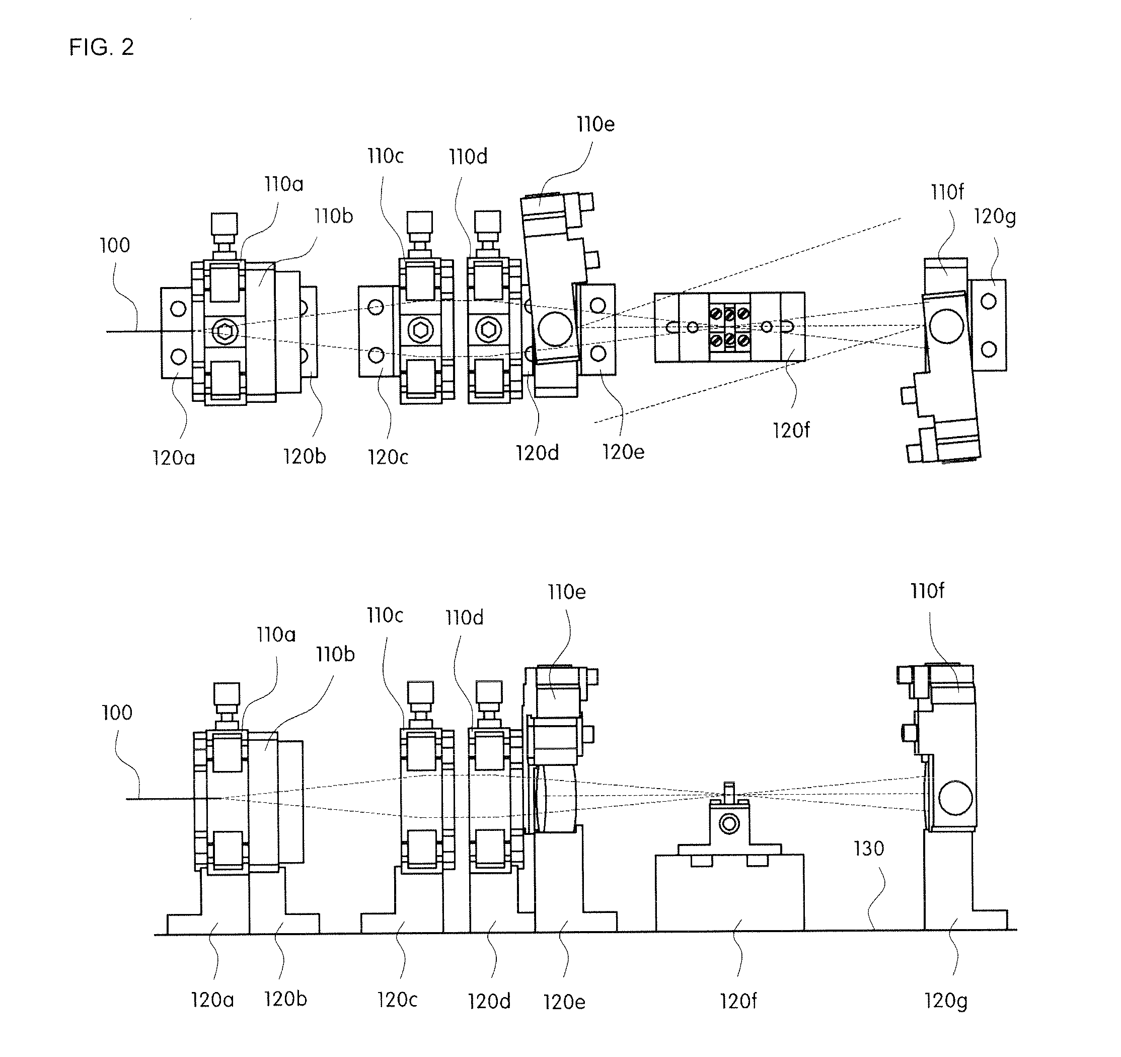
[0100]FIG. 4 shows a front view and a plane view of an optical pumping unit in which optical mounts are modularized as one piece, according to the present invention.

[0101]As shown in FIG. 4, a femtosecond laser apparatus according to ...


PUM


Abstract

The present invention provides a femtosecond laser apparatus using laser diode optical pumping. To provide a stable mode locking and improve power stability and beam stability in an ultrafast laser such as a femtosecond laser, optical mounts which have mounted thereon optical parts of a diode pumping unit are mechanically engaged using bars of low thermal expansion coefficients and form a pumping module, and the pumping module is maximally separated from a laser platform or case.

Description

CROSS-REFERENCE TO RELATED APPLICATION[0001]This application claims under 35 U.S.C. §119(a) the benefit of Korean Patent Application No. 10-2011-0083563 filed Aug. 22, 2011, the entire contents of which are incorporated herein by reference.BACKGROUND[0002](a) Technical Field[0003]The present disclosure relates to a diode-pumped laser apparatus. More particularly, it relates to a femtosecond laser apparatus using a laser diode optical pumping module, which can provide stable mode locking and can improve power stability and beam stability in a ultrafast laser.[0004](b) Background Art[0005]In general, an ultrafast laser pulse has superior properties such as high peak power, a large spectral width, etc., as well as a short pulse time width.[0006]The ultrafast laser system, due to such properties thereof, has been used for ultra-precision micromachining of various materials, non-linear optics, and bio, chemical, physical, and medical applications, and so forth.[0007]For example, because ...

Claims


Application Information

Patent Timeline
Patent Type & Authority Applications(United States)
IPC IPC(8): H01S3/098
CPCH01S3/08059H01S3/0811H01S3/025H01S3/1118H01S5/02415H01S3/09415H01S5/02253H01S5/02251H01S5/041
Inventor KIM, GUANG HOONKANG, UKYANG, JU HEESALL, ELENACHIZHOV, SERGEYKULIK, ANDREY
Owner KOREA ELECTROTECH RES INST
Learn More