
Common rail having orifice

a common rail and orifice technology, applied in the direction of liquid fuel feeders, fuel injecting pumps, machines/engines, etc., can solve the problems of difficult to ensure a safety margin related to fatigue strength, change in the inner diameter of the orifice , change in the injection characteristics of the injector, so as to achieve sufficient reduction of injection pressure difference and injection amount difference between the cylinders, and attenuation of pressure pulsation.

Active Publication Date: 2009-04-14
DENSO CORP
View PDF23 Cites 22 Cited by
  • Summary
  • Abstract
  • Description
  • Claims
  • Application Information

AI Technical Summary

Benefits of technology

The present invention provides a common rail that can prevent changes in the inner diameter of a small diameter orifice in a bush when the bush is inserted into an inside-outside communication hole. It also prevents deformation of an external screw on a pipe joint when the bush is press-fitted into the hole. The common rail can restrict injection pressure difference and injection amount difference among cylinders of an internal combustion engine by restricting a pressure wave. Additionally, the common rail can reduce pressure pulsation and stabilize pressure inside a pressure accumulation chamber of a cylindrical section, thereby inhibiting an influence on injection characteristics of each cylinder. The orifice forming member can be slidably provided in a cylinder to attenuate pressure pulsation and stabilize pressure inside the pressure accumulation chamber. A large diameter hole connecting the orifice with the inside-outside communication hole can be formed in the orifice forming member to shorten the process length of the orifice and reduce costs.

Problems solved by technology

However, since the crossing hole of the orifice α is small in the common rail 201 with the orifice α formed integrally in the rail main body 220 by the hole making process, it is difficult to ensure a safety margin related to fatigue strength.
Therefore, there is a possibility that an inner diameter of the orifice α is changed by distortion caused by the press-fitting.
As a result, there is a possibility that injection characteristics of the injector change and designed injection cannot be performed.
IF the external screw 225 is deformed, there is a possibility that a trouble is caused in screwing of a pipe nut for fixing the external pipe to the joint 221.
The propagation of the reflection wave, which is caused by the opening and closing of the injector, to the inside of the pressure accumulation chamber of the common rail cannot be prevented sufficiently by only providing the orifice in the inside-outside communication hole or the fuel passage.
As a result, a cost is increased.
Therefore, the number of the parts is increased, increasing a cost.
In this common rail, selection of spring constants of the first and second springs for damping the pressure pulsation and the reflection waves is difficult.
For example, it is difficult to decide which spring constant should be increased out of the spring constants of the first and second springs.
Therefore, the pressure waves (discharge pulsation of fuel supply pump and reflection waves from injectors) significantly affecting the injection amount characteristics (injection timing, injection amount, injection ratio and the like) of each cylinder of the engine cannot be sufficiently restricted to be small.
The influence of the pressure pulsation inside the pressure accumulation chamber of the common rail on the valve opening timing, the valve closing timing and the fuel injection pressure of the same cylinder or the other cylinder cannot be eliminated.
As a result, the difference in the injection pressure or the injection amount among the cylinders cannot be sufficiently restricted to be small.

Method used


Image

  • Common rail having orifice
  • Common rail having orifice
  • Common rail having orifice

Examples


Embodiment Construction

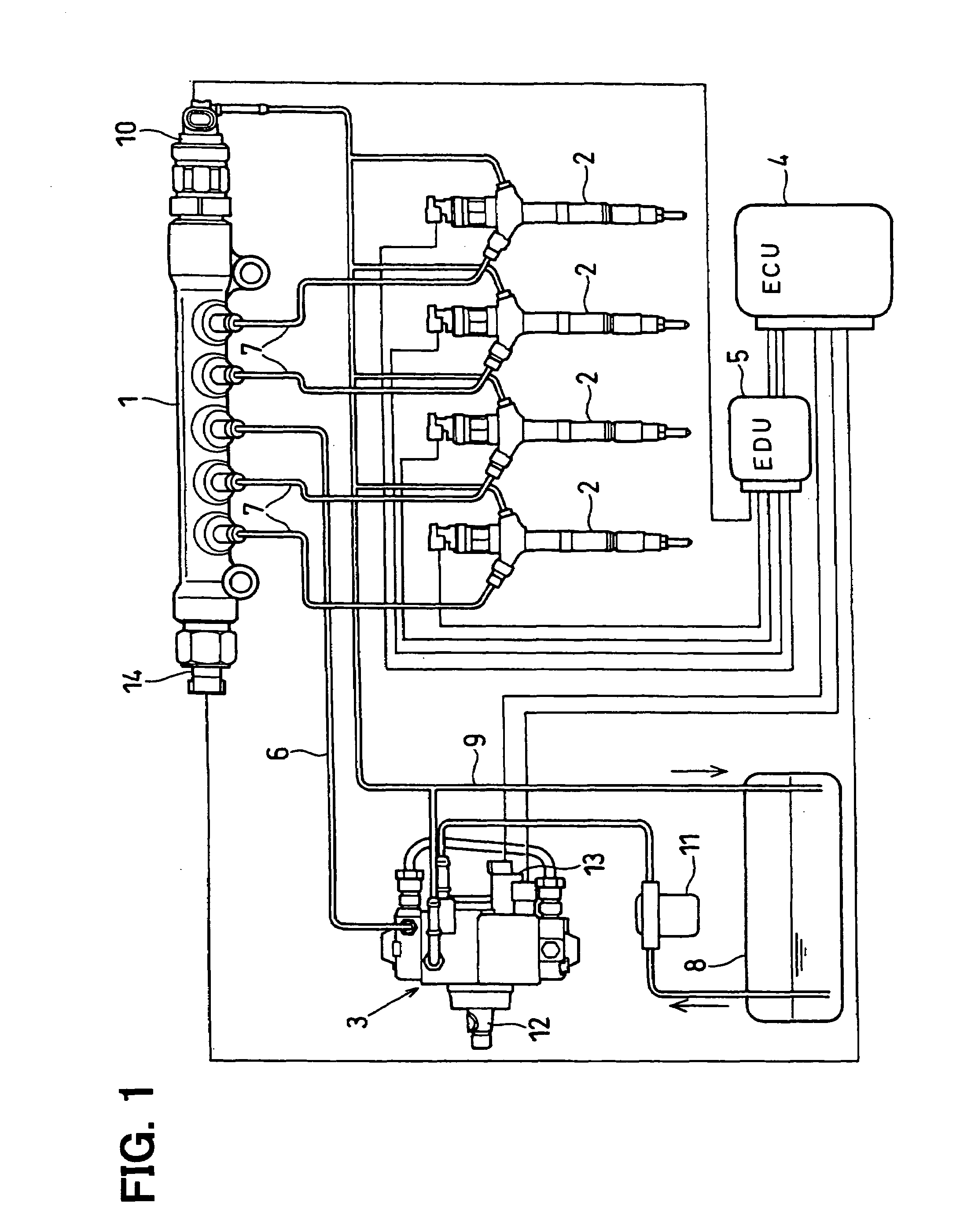
[0055]Referring to FIG. 1, a pressure accumulation fuel injection device according to a first example embodiment of the present invention is illustrated. The fuel injection device shown in FIG. 1 is a system for performing fuel injection into respective cylinders of an engine (for example, a diesel engine, not shown). The fuel injection device has a common rail 1, injectors 2, a supply pump 3, an engine control unit (ECU) 4, a drive unit (EDU) 5 and the like. The EDU 5 may be incorporated in a casing of the ECU 4.

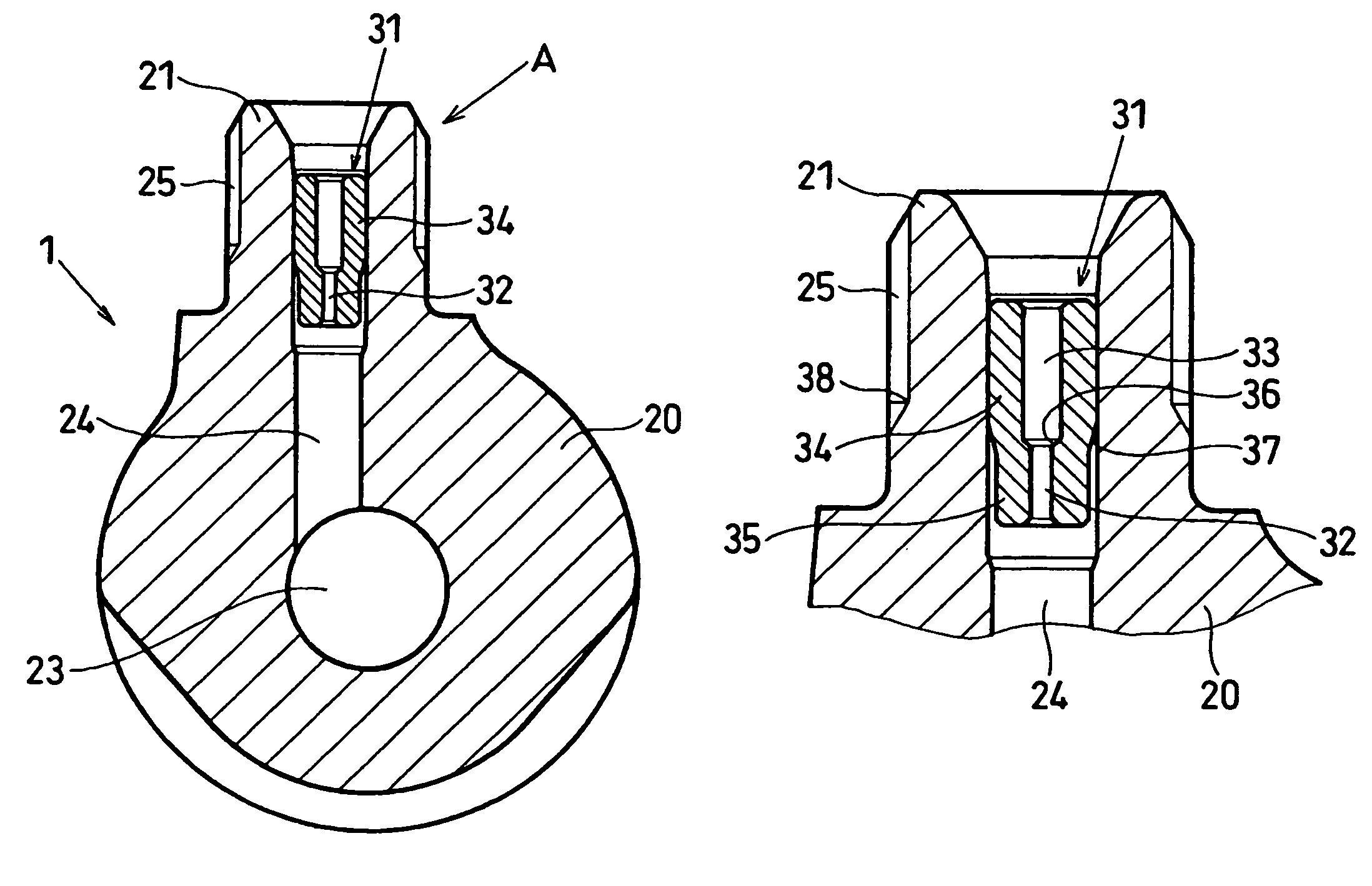
[0056]The common rail 1 is a pressure accumulation vessel for accumulating high-pressure fuel to be supplied to the injectors 2. In order to accumulate common rail pressure corresponding to fuel injection pressure, the common rail 1 is connected with a discharge hole of the supply pump 3, which pressure-feeds the high-pressure fuel, through a high-pressure pump pipe 6. The common rail 1 is also connected with multiple injector pipes 7 for supplying the high-pressure fuel to...


PUM


Abstract

A bush incorporated in a common rail is formed with a smallest diameter orifice having a small inner diameter and an adjacent orifice having an inner diameter larger than that of the smallest diameter orifice on an inner peripheral face of the bush. A press-fitted portion, which is press-fitted into an inside-outside communication hole, and a non-press-fitted portion, which has a smaller outer diameter than the press-fitted portion, are formed on an outer peripheral face of the bush. The smallest diameter orifice and the press-fitted portion are deviated from each other in an axial direction of the bush to prevent an overlap in a radial direction of the bush. Thus, even if the bush is tightly press-fitted into the inside-outside communication hole, decrease of the inner diameter of the smallest diameter orifice can be averted.

Description

CROSS REFERENCE TO RELATED APPLICATION[0001]This application is based on and incorporates herein by reference Japanese Patent Applications No. 2006-12478 filed on Jan. 20, 2006, No. 2006-42336 filed on Feb. 20, 2006 and No. 2006-242946 filed on Sep. 7, 2006.BACKGROUND OF THE INVENTION[0002]1. Field of the Invention[0003]The present invention relates to a common rail mounted in a pressure accumulation fuel injection device for accumulating high-pressure fuel.[0004]2. Description of Related Art[0005]A pressure accumulation fuel injection device is known as a fuel supply device of an internal combustion engine such as a diesel engine for pressurizing fuel suctioned from a fuel tank with a pump and for supplying the fuel into combustion chambers of respective cylinders of the engine from injectors through injection. The pressure accumulation fuel injection device has a common rail for accumulating high-pressure fuel discharged by a fuel supply pump. The pressure accumulation fuel inject...

Claims


Application Information

Patent Timeline
Patent Type & Authority Patents(United States)
IPC IPC(8): F02M69/46F02M55/02
CPCF02M55/025F02M55/04F02M2200/315F02M2200/28
Inventor TOMINAGA, TAKASHINISHIWAKI, TADASHI
Owner DENSO CORP
Learn More