
Formatting of phase-change optical disc for improved signal characteristics

a phase-change optical disc and signal characteristics technology, applied in the field of data recording method for recording information on a phase-change rewritable optical disc, can solve the problems of optical disc drive, difficult mass production of optical discs, and inability to detect defective sectors or perform re-allocation processing on defective sectors. , to achieve the effect of improving the reliability of playback signals

Inactive Publication Date: 2009-03-31
RICOH KK
View PDF21 Cites 2 Cited by
  • Summary
  • Abstract
  • Description
  • Claims
  • Application Information

AI Technical Summary

Benefits of technology

[0022]Accordingly, in view of the above-described background, it is an object of the present invention to provide a data recording method for allowing mass production of optical discs which are subjected to high quality formatting processing.
[0023]It is another object of the present invention to provide a phase-change optical disc formatting method for allowing efficient mass production of formatted high-quality phase-change optical discs, and also to provide phase-change optical discs formatted by this method.
[0024]It is still another object of the present invention to provide a recording method and device in which optical recording media can be prevented from being deteriorated by the overwriting of user data, and to provide optical recording media in which data is recorded by the above-described recording method.
[0025]It is a further object of the present invention to provide an optical disc and an optical-disc write protection method in which data can be protected from being lost by a user.
[0035]According to the above-described data recording method, signal characteristics of the user data area are higher than those of the format area, thereby improving the reliability of playback signals.

Problems solved by technology

In contrast, an optical disc drive, such as a compact disc rewritable (CD-RW) drive, for recording and playing back phase-change optical discs, such as CD-RW discs, cannot detect defective sectors or perform re-allocating processing on the defective sectors.
It is thus difficult to mass-produce optical discs which are subjected to formatting processing compatible with a plurality of types of applications.
The discs formatted as described above are not suitable for mass production, and also, jitter becomes larger in the area in which the file structure or the data application is recorded than in the format area, resulting in a lower-quality recorded signal.
Thus, such discs cannot be played back by another drive.
However, when the same link block data “0” is always written into the same physical position before and after writing the user data, physical noise is accumulated in the link block of the recording medium, thereby increasing the jitter.
Particularly in a recording medium, such as in a database, in which user data is frequency overwritten, the same link block data is written into the same link block every time user data is overwritten, thereby increasing the jitter.
As a result, the optical recording medium cannot be overwritten any longer before maximum overwriting operations are performed.
In contrast, a disc which is not housed in a cartridge, such as a CD-RW disc, mechanical write protection means are not provided, and thus, it is difficult to protect data from being erased or overwritten in a CD-RW disc.
However, as discussed above, since a write protection function is not provided for current CD-RW discs or packet writings software, a user may erroneously overwrite, erase, or format CD-RW discs.
As a result, important data may be lost.

Method used


Image

  • Formatting of phase-change optical disc for improved signal characteristics
  • Formatting of phase-change optical disc for improved signal characteristics
  • Formatting of phase-change optical disc for improved signal characteristics

Examples


first embodiment

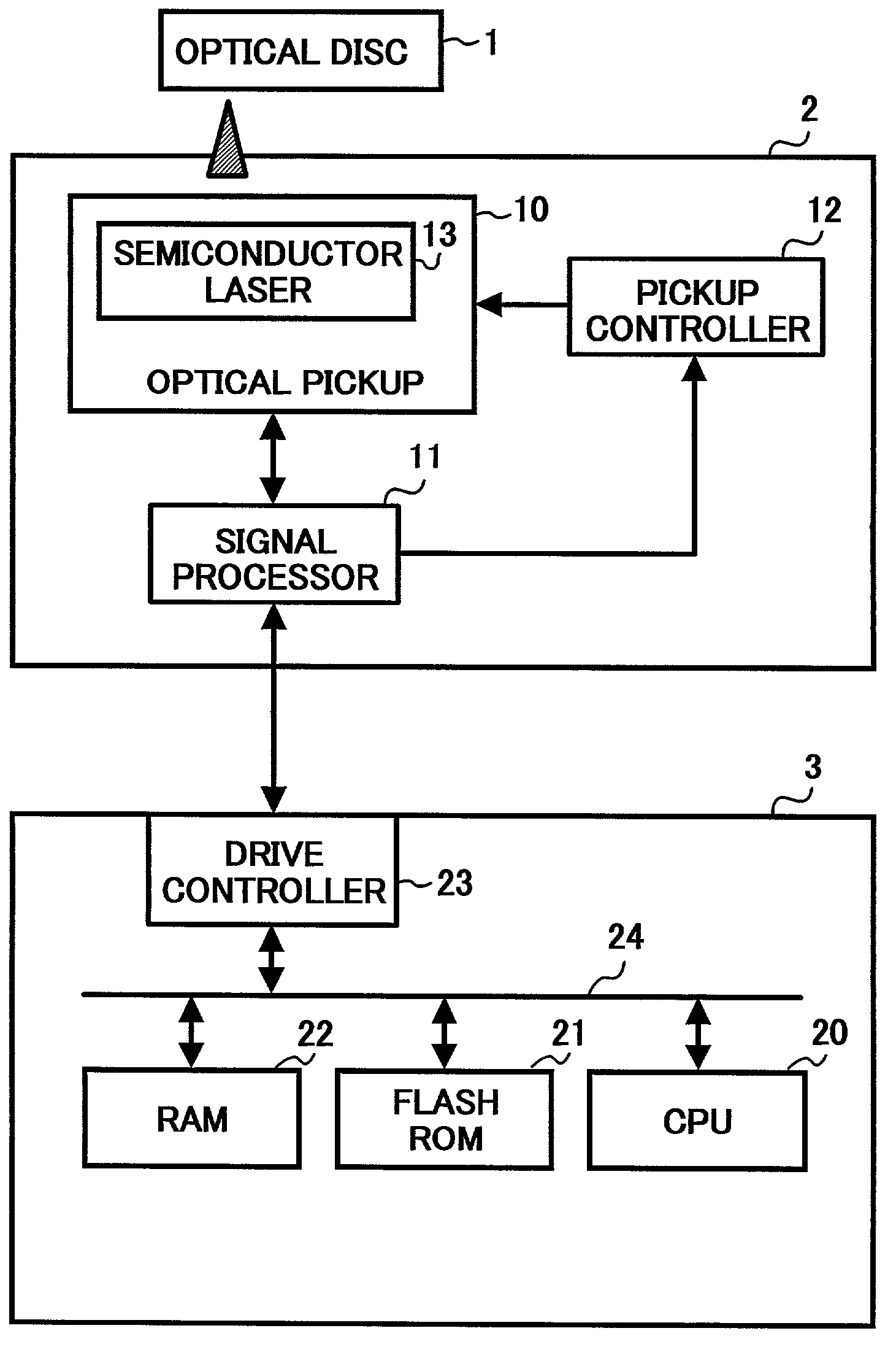
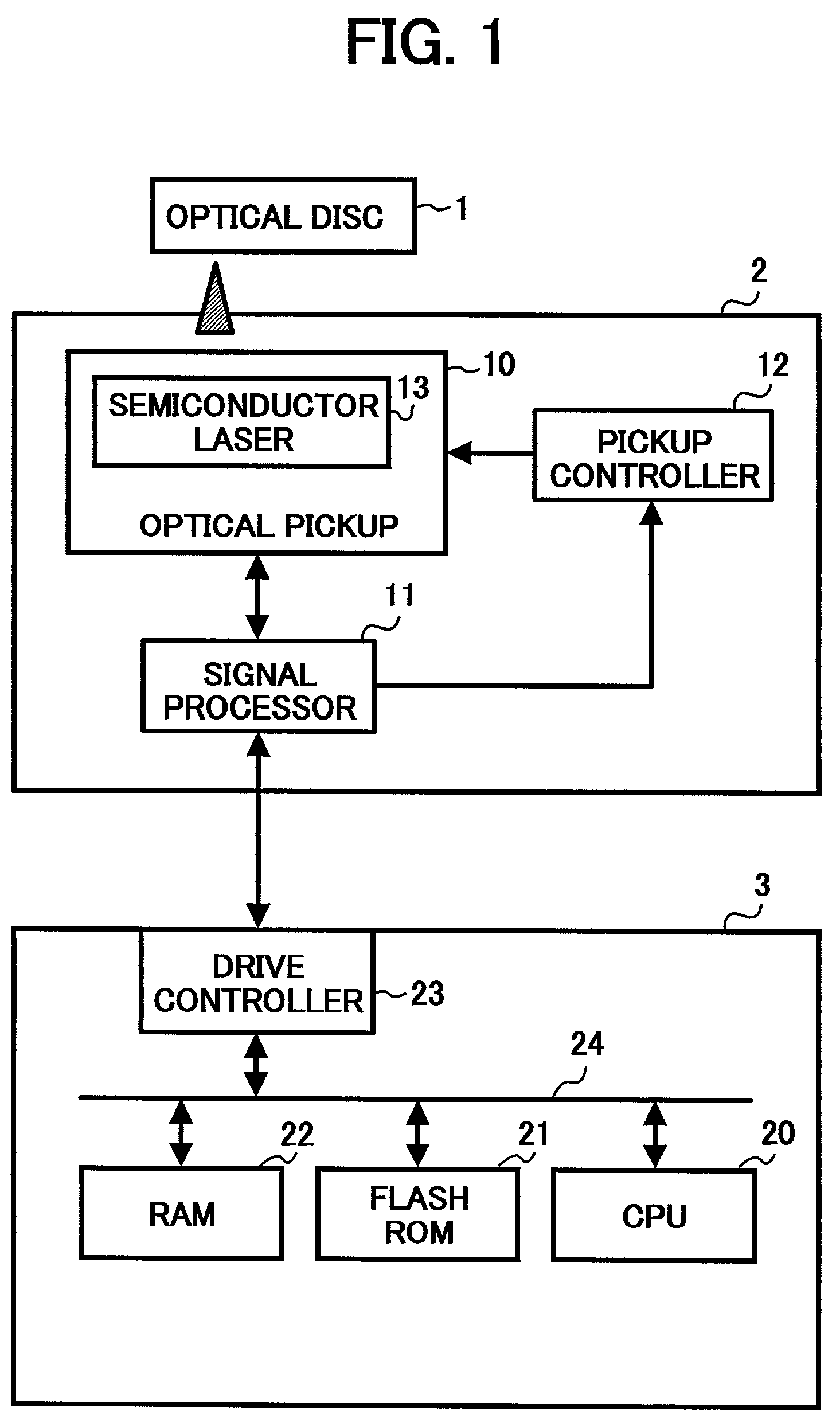
[0053]FIG. 1 illustrates an optical disc device using a data recording method of the present invention. The optical disc device shown in FIG. 1 is used for recording and playing back information to and from an optical disc 1, and includes an optical disc drive 2 and a control unit 3.

[0054]The optical disc 1 is a rewritable recording carrier, such as a CD-RW disc, utilizing a change in optical characteristics (transmittance or reflectance) caused by a phase change. By applying a light beam to the optical disc 1, information can be recorded or played back. More specifically, a light beam is applied to a track of the recording layer of the optical disc 1 in a highly crystalline state so as to increase the temperature to the melting point of the recording layer material or higher. Accordingly, a transition occurs in the track from the highly crystalline state to an amorphous state having lower crystallinity, thereby forming pits in which information can be recorded.

[0055]Information is ...

second embodiment

[0098]A phase-change optical disc formatting device constructed in accordance with the present invention is discussed below with reference to FIGS. 3, 4A, and 4B.

[0099]The phase-change optical disc formatting device shown in FIG. 3 includes an optical disc drive 31, a CPU (control means) 32 for controlling the optical disc drive 31, a flash ROM (storage means) 33 for storing information unique to applications, such as UDF data and a file structure, and also for storing a format program to be executed, a drive interface 34, such as an ATAPI or a SCSI, an operation / display panel 35, an operation / display panel interface 36, and a RAM 37 used as a work area by the CPU 32. The CPU 32, the flash ROM 33, the drive interface 34, the operation / display panel interface 36, and the RAM 37 are mounted on a drive control circuit (not shown).

[0100]UDF stands for Universal Disk Format, which is a standard defined by the Optical Storage Technology Association (OSTA), and is standardized by ISO 13346...

third embodiment

[0110]the present invention is described below with reference to FIGS. 5 through 10.

[0111]A CD-RW drive, which serves as an optical recording device of the present invention, includes a drive controller 41, as shown in FIG. 6. The drive controller 41 transmits and receives information to and from a microcomputer 42, a buffer 43, a host computer 44, a rotation controller 45, a laser controller 46, an actuator controller 47, and a signal controller 48. The drive controller 41 transmits and receives information to and from the host computer 44 via an interface (not shown).

[0112]An optical recording medium (CD-RW disc) 60 is placed on a tray 49, and the rotation controller 45 controls the operation of a spindle motor 50 to rotate the optical recording medium 60. The laser controller 46 controls a semiconductor laser of an optical pickup 51 to be turned ON or OFF. The actuator controller 47 drives the optical pickup 51 to move vertically and horizontally so that data is read and written ...


PUM


Abstract

A phase-change optical disc formatting device which formats a phase-change optical disc so that signal characteristics of an area in which at least one of a file structure and application data is to be recorded are substantially equal to signal characteristics of a format area. A phase-change optical disc formatting method including: formatting a phase-change optical disc so that signal characteristics of an area in which at least one of a file structure and application data is to be recorded are substantially equal to signal characteristics of a format area. A phase-change optical disc formatted such that signal characteristics of an area of the phase-change optical disc in which at least one of a file structure and application data is to be recorded are substantially equal to signal characteristics of a format area of the phase-change optical disc.

Description

BACKGROUND OF THE INVENTION[0001]1. Field of the Invention[0002]The present invention relates to a data recording method for recording information on a phase-change rewritable optical disc, and more particularly, to a data recording method for allowing mass production of optical discs which are subjected to high-quality formatting processing. The invention also pertains to a device and method for formatting phase-change optical discs, and a phase-change optical disc formatted by this method. The invention also relates to a method and a device for recording rewritable recording media, and to optical recording media on which data is recorded by this method. The invention also pertains to a write protection method for optical discs.[0003]2. Discussion of the Related Art[0004]For formatting a magneto-optical (MO) disk, an MO disk drive for recording and playing back information to and from the MO disk detects defective sectors on the disk, registers them on a primary defect list (PDL), ...

Claims


Application Information

Patent Timeline
IPC IPC(8): G11B7/24G11B5/76G11B7/0045G11B7/006G11B7/007G11B7/26G11B20/10
CPCG11B7/268G11B20/10G11B20/10009G11B20/10212G11B7/00454G11B7/006G11B7/00745G11B2020/10898
Inventor OHMI, FUMIYA
Owner RICOH KK
Learn More