
Power measuring apparatus

a technology of power measurement and power measurement device, which is applied in the direction of electric variable regulation, process and machine control, instruments, etc., can solve the problems of further increase in the uncertainty of power measurement and low efficiency of thermal testing, so as to advance the operation efficiency and quality of thermal testing and increase the accuracy of power measurement.

Inactive Publication Date: 2009-03-31
INVENTEC CORP
View PDF5 Cites 49 Cited by
  • Summary
  • Abstract
  • Description
  • Claims
  • Application Information

AI Technical Summary

Benefits of technology

[0007]Accordingly, the present invention is directed to a power measuring apparatus, which is able to instantly measure the power of a CPU and each chipset so as to promote the working efficiency and quality and increase the accuracy of thermal test.
[0015]In summary, the present invention uses a voltage-current measuring device to convert the output voltage signal generated by a power converter into a voltage feedback signal. Further, a terminal current signal is obtained by measuring the voltage across the terminals of the first capacitor. Moreover, an operation unit is used to conduct operations on the voltage feedback signal and the terminal current signal so as to obtain the measured power. According to the measurement scheme of the present invention, variations of the voltage feedback signal and the terminal current signal can instantaneously affect the output of the operation unit, which enables to increase the accuracy of power measurement and advance the operation efficiency and quality of thermal test.

Problems solved by technology

In particular, the variations of the operation efficiency of the computer system or the server and the voltage identification code signal (VID signal) are hard to control, thus, the uncertainty of power measurement is further increased, which results in a low efficiency of thermal test.

Method used


Image

  • Power measuring apparatus
  • Power measuring apparatus
  • Power measuring apparatus

Examples


Embodiment Construction

[0019]Reference will now be made in detail to the present preferred embodiments of the invention, examples of which are illustrated in the accompanying drawings. Wherever possible, the same reference numbers are used in the drawings and the description to refer to the same or like parts.

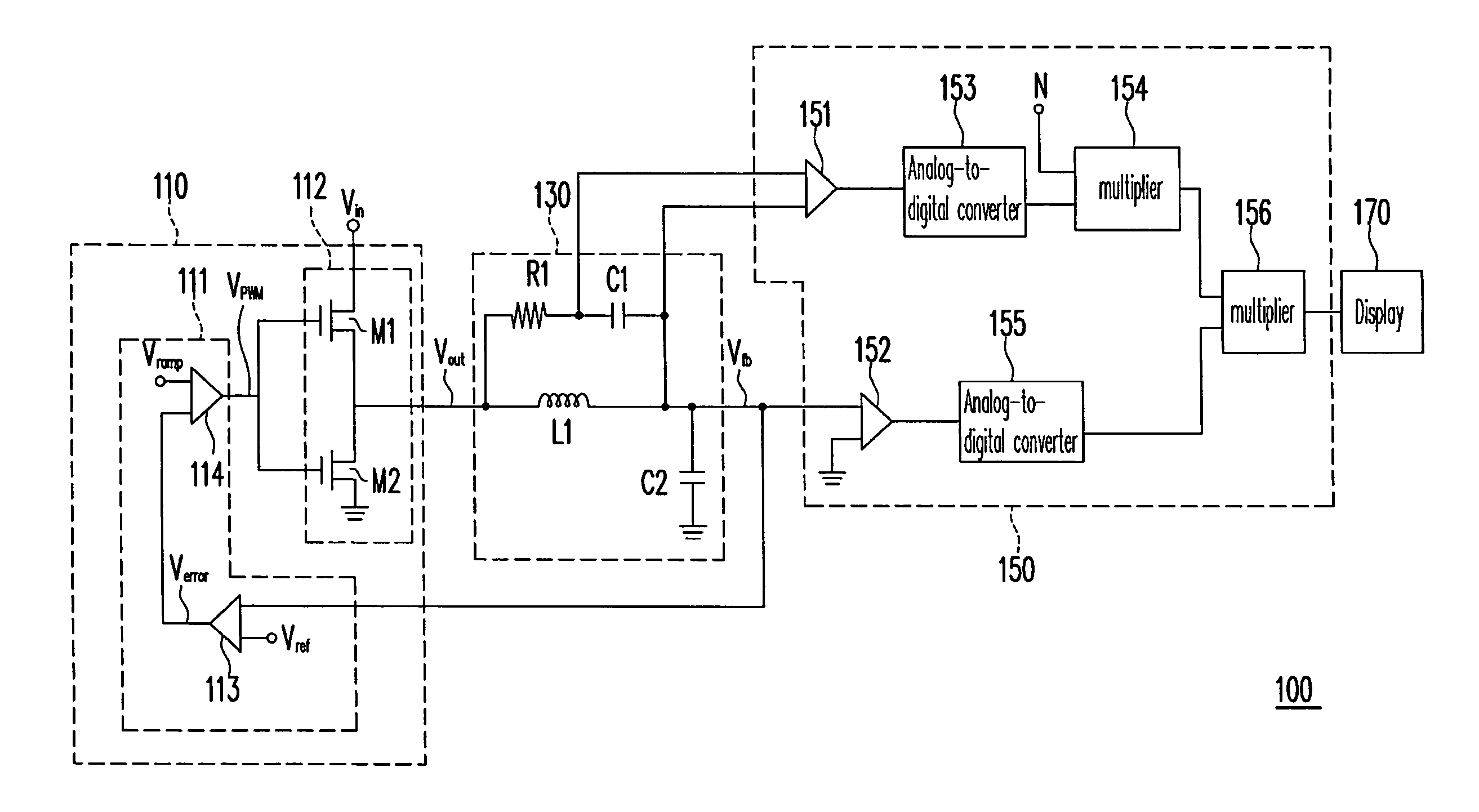
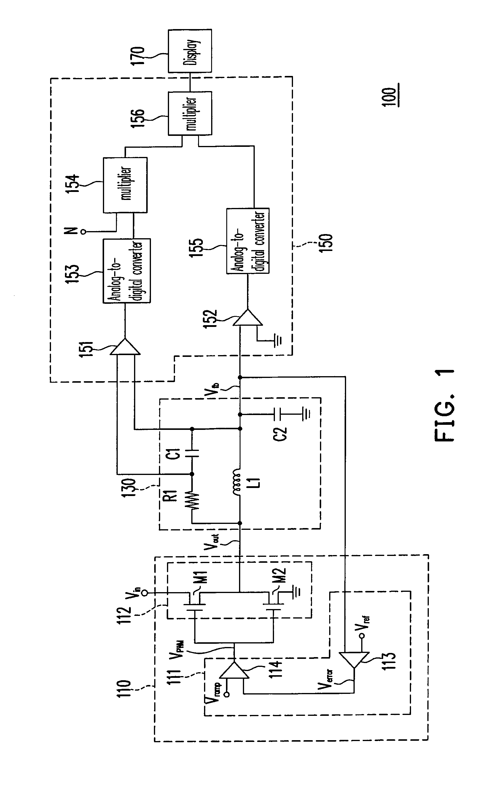
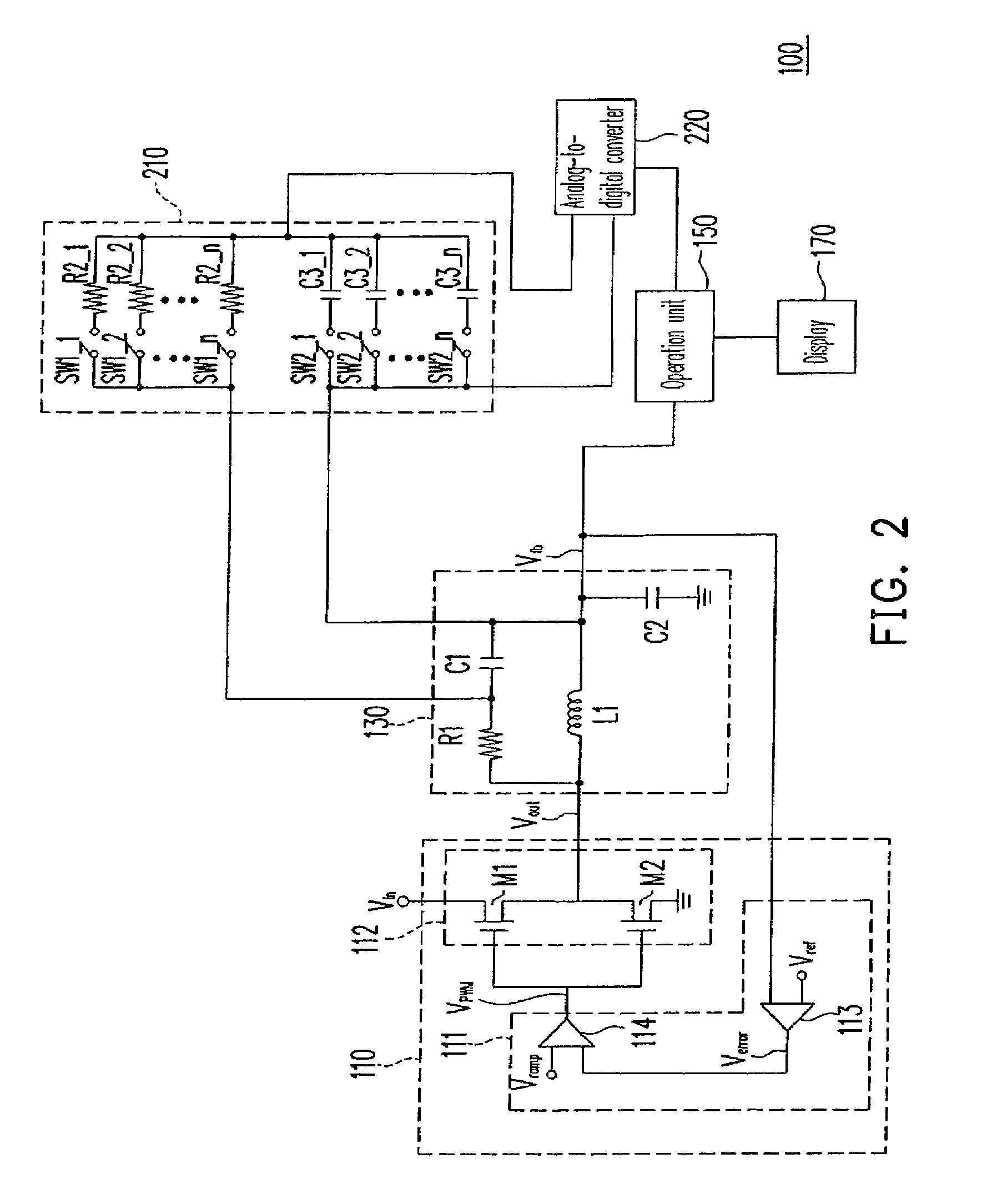
[0020]FIG. 1 is a circuit diagram of a power measuring apparatus according to an embodiment of the present invention. Referring to FIG. 1, a power measuring apparatus 100 includes a voltage transformer 110, a voltage-current measuring circuit 130, an operation unit 150 and a display 170.

[0021]The voltage transformer 110 includes a PWM unit 111 and a switch unit 112, wherein the PWM unit 111 includes an error amplifier 113 and a comparator 114. The error amplifier 113 receives a voltage feedback signal Vfb and compares the voltage feedback signal Vfb with a voltage reference signal Vref to generate an error signal Verror output to the comparator 114. The comparator 114 receives the error signal Verror...


PUM


Abstract

A power measuring apparatus including a voltage transformer, a voltage-current measuring circuit, and an operation unit is provided. The voltage transformer converts an input voltage signal into an output voltage signal. The voltage-current measuring circuit includes an inductor, a first resistor, a first capacitor and a second capacitor. A first end of the first inductor herein receives the output voltage signal and a second end thereof generates a voltage feedback signal. The operation unit performs an operation on the voltage feedback signal and a terminal current signal between the first terminal and the second terminal of the first capacitor so as to calculate a power signal. In this way, the accuracy of thermal test is effectively increased by the presented invention.

Description

CROSS-REFERENCE TO RELATED APPLICATION[0001]This application claims the priority benefit of Taiwan application serial no. 96143770, filed on Nov. 19, 2007. The entirety of the above-mentioned patent application is hereby incorporated by reference herein and made a part of this specification.BACKGROUND OF THE INVENTION[0002]1. Field of the Invention[0003]The present invention generally relates to a power measuring apparatus, and more particularly, to a power measuring apparatus capable of increasing the accuracy of thermal test.[0004]2. Description of Related Art[0005]In a computer system or a server today, the center processing unit (CPU) thereof has increasing operation efficiency and operation frequency. In order to assure the stability of a computer system or server, conducting thermal test is a routine procedure, wherein a key point of the thermal test is to measure the power thereof as the CPU or the chipset runs in the maximum power.[0006]However, during conducting thermal tes...

Claims


Application Information

Patent Timeline
Patent Type & Authority Patents(United States)
IPC IPC(8): G01R7/00G01R11/32G05F1/00H02M3/24H02M5/42H02M7/44H02M7/68
CPCG01R21/133H02M3/156H02M2001/0009H02M1/0009
Inventor XIA, CHUN-HUAHUANG, LI-HONGLIU, SHIH-HAO
Owner INVENTEC CORP
Learn More