Method and apparatus for the production of hydrogen-rich gas

a technology of hydrogen-rich gas and process, which is applied in the direction of lighting and heating apparatus, machines/engines, and separation processes, etc., can solve the problems of large temperature rise across the shift reactor, affecting steam consumption, and the reaction rate of iron oxide catalysts at low temperatures is comparatively slow, so as to prevent over-reduction of the shift catalyst

Active Publication Date: 2009-03-31
AIR PROD & CHEM INC
View PDF13 Cites 3 Cited by
  • Summary
  • Abstract
  • Description
  • Claims
  • Application Information

AI Technical Summary

Benefits of technology

[0022]In the present invention, the risk of over-reduction of iron oxide-based shift catalyst resulting in structural deterioration of the catalyst may be avoided by directly or indirectly adding an oxidative stream to a gaseous feed stream to the shift reactor and / or to provide at least two gaseous feed streams to at least two regions of shift catalyst, thereby maintaining criteria for preventing over-reduction of the shift catalyst.
[0026]Prior art fails to teach a method including production of synthesis gas in a catalytic steam reformer coupled with the addition of an oxidative stream to the feed stream comprising synthesis gas to a shift reactor wherein the oxidative stream is derived from at least one of a side stream from the shift reactor, a product stream of the shift reactor after cooling in a heat exchanger, a side stream or product stream from another shift reactor, pure or enriched CO2 streams from CO2 separation units, a combustion reactor effluent stream, a selective oxidation reactor effluent stream, hydrogen pressure swing adsorption purge gas streams, a hydrogen pressure swing adsorption feed gas stream, and other CO2-rich streams from the hydrogen plant, a refinery, a chemical plant, or other nearby process so as to prevent over-reduction of iron oxide-based shift catalyst, thereby limiting structural deterioration of the catalyst.

Problems solved by technology

However, a serious disadvantage is that the reaction rate of iron oxide catalysts at low temperatures is comparatively slow.
The temperature rise across the shift reactor is generally a limitation affecting steam consumption in partial oxidation (POX) and gasification-based hydrogen production processes.
Since the shift reaction is exothermic, conversion of large amounts of CO in the syngas from a POX unit or a gasification unit releases a large amount of heat, causing large temperature rise across the shift reactor, which leads to catalyst deactivation by sintering.
This excess use of steam, however, reduces the the thermal efficiency of the process.
If the catalyst is reduced further to wustite (FeO) or completely to iron metal (Fe°), its strength will decrease to a point where it begins to lose its physical integrity.
A further problem with over-reduction is that both wustite and iron metal can catalyze the Fischer-Tropsch reaction.
Control of the relative concentrations of CO, CO2, H2 and H2O is difficult for all sources of feed gas to the shift reactor.
For example, for feed gas from a catalytic steam reformer, measurement is difficult and the actual composition depends on many variables such as the reforming temperature and pressure and the ratio of hydrogen to carbon to oxygen atoms in the feed gas to the reformer.
Additionally, it is hard to know what the limits to prevent over-reduction actually are since the catalyst damage (over-reduction) comes before the symptoms (byproduct formation and increased pressure drop).
As the S / C ratio declined, catalyst manufacturers and operators struggled to define the acceptable operating range of S / C ratio for the high temperature shift.
In the catalytic steam reforming case, increasing the outlet temperature of the reformer, increasing the pressure, and / or decreasing the steam to feedstock carbon ratio (steam-to-carbon ratio) in the reformer feed, all tend to increase the risk of over-reduction of the shift catalyst in the subsequent shift reactor stage.
However the generation of such an excess of steam is not energy efficient and, in the interests of economy, it is desirable to operate steam reforming processes at low steam-to-carbon ratios.
Unfortunately, the economic benefits that were achieved by lowering the steam-to-carbon ratio into the catalytic steam reformer process are essentially cancelled out due to the efficiency penalty associated with the added steam injected upstream of the HTS reactor.

Method used


Image

  • Method and apparatus for the production of hydrogen-rich gas
  • Method and apparatus for the production of hydrogen-rich gas
  • Method and apparatus for the production of hydrogen-rich gas

Examples


example 1

Base Case

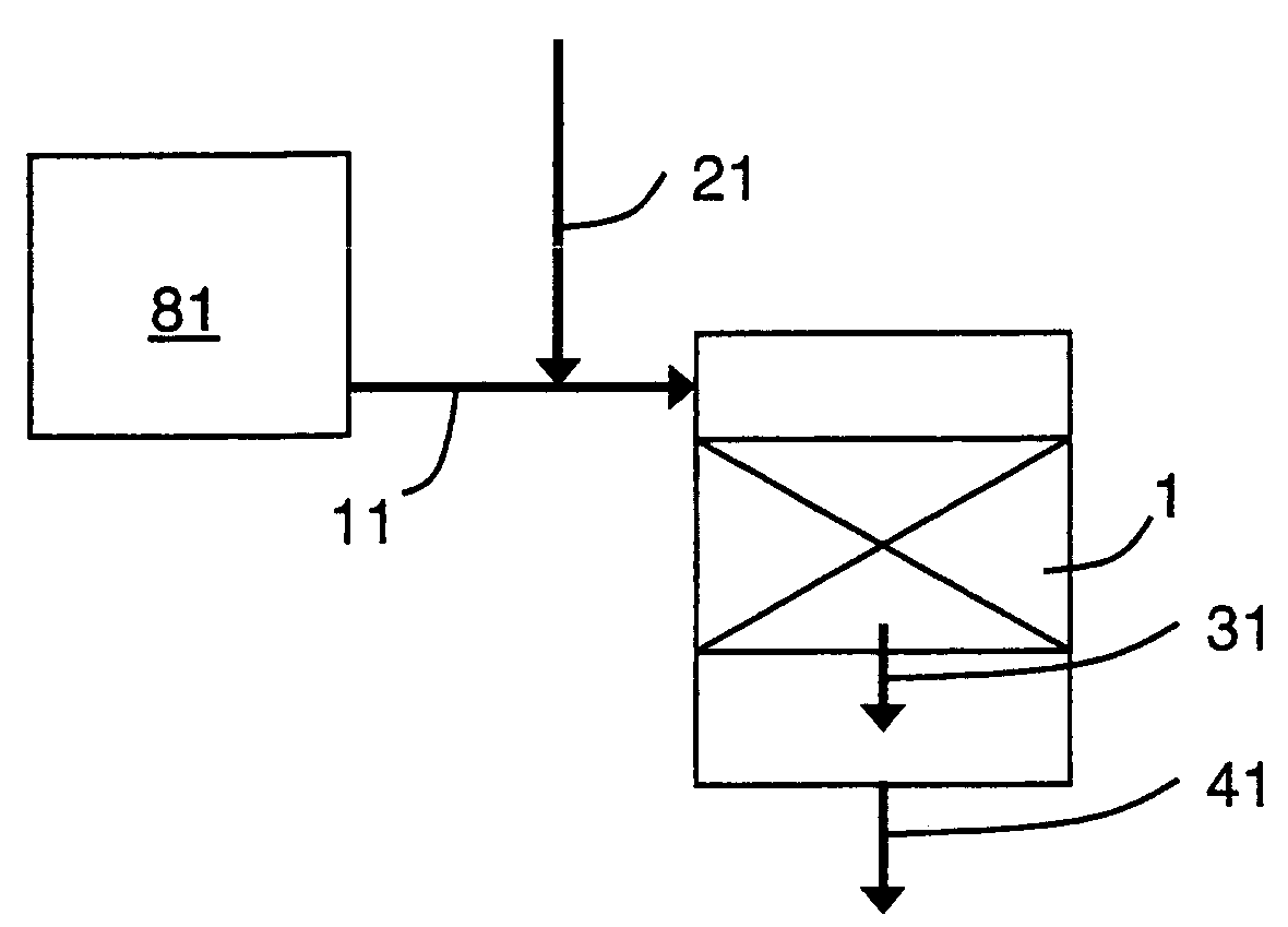
[0073]The base case has one catalyst region, similar to FIG. 1, but without the oxidative stream 21. The base case serves as a basis for comparison for efficiency improvement and over-reduction. For the base case, the reformer feed stream has a steam to carbon (steam-to-carbon) ratio of 3. The reformer effluent, which is the gaseous feed stream 11 to the shift reactor has a CO / CO2 ratio of 1.61 and a steam-to-dry-gas ratio of 0.54. The thermal efficiency of H2 production will be normalized with the thermal efficiency of the base case, giving a value of 1 for the base case.

[0074]With a feed to the reformer having a steam to carbon ratio of 3, the primary criterion to prevent over-reduction of catalyst, CO / CO2≦1.61, is satisfied.

example 2

Reduced Steam and No Oxidative Stream

[0075]There is incentive to reduce the amount of steam to the catalytic steam reformer. This improves the overall efficiency of the process.

[0076]Example 2 has one catalyst region, similar to FIG. 1, but without the oxidative stream 21. The reformer feed stream has a reduced steam to carbon ratio of 2.5. In this case the reformer effluent, which is the gaseous feed stream 11 to the shift reactor has a CO / CO2 ratio of 1.86 and a steam-to-dry-gas ratio of 0.46. The normalized thermal efficiency is calculated to be 1.015, a 1.5% improvement over the base case, thereby illustrating the incentive to reduce the steam-to-carbon ratio to the reformer.

[0077]But in this case, neither criterion for preventing over-reduction of the catalyst is satisfied. The CO / CO2 ratio is 1.86, which is greater than the maximum 1.61, and the steam-to-dry-gas ratio is 0.46, which is less than the minimum 0.6.

example 3

Oxidative Stream from Shift Reactor Product Stream

[0078]Example 3 has one catalyst region, similar to FIG. 1, with the oxidative stream 21. The reformer feed stream has a reduced steam to carbon ratio of 2.5. In this case the reformer effluent, which is the gaseous feed stream 11, is blended with an oxidative stream 21, which in this example is a slipstream of the product stream 41 from the shift reactor, after being cooled considerably, but still above the dew point, to facilitate recycle compression. The molar ratio of stream 21 to stream 11 is 0.085. The blended stream to the shift reactor then has a CO / CO2 ratio of 1.61. The normalized thermal efficiency is calculated to be 1.014, a 1.4% improvement over the base case.

[0079]In this example, the primary criterion for preventing over-reduction of the catalyst is satisfied. A similar thermal efficiency improvement to example 2 is provided while keeping the catalyst in a safe regime.


PUM

PropertyMeasurementUnit
molar ratioaaaaaaaaaa
temperaturesaaaaaaaaaa
temperatureaaaaaaaaaa

Abstract

A method and apparatus for the production of hydrogen-rich gas are provided. The method and apparatus prevent over-reduction of iron oxide-based shift catalyst by introducing an oxidative stream along with a carbon monoxide containing gaseous feed stream from a catalytic steam reformer to the catalyst bed region and thereby limits structural deterioration of the catalyst. Various sources may provide the oxidative stream including a shift catalyst bed region and a selective oxidation catalyst region.

Description

CROSS-REFERENCE TO RELATED APPLICATIONS[0001]This application is a continuation-in-part of application Ser. No. 11 / 052,253 filed on Feb. 7, 2005 now abandoned.STATEMENT REGARDING FEDERALLY SPONSORED RESEARCH OR DEVELOPMENT[0002]None.BACKGROUND OF THE INVENTION[0003]This invention relates to a continuous process for the production of hydrogen-rich gas. More specifically, the present invention pertains to a method and apparatus for preventing over-reduction of iron oxide-based shift catalyst thereby limiting structural deterioration of the catalyst.[0004]Hydrogen gas may be obtained by the catalytic reaction of carbon monoxide and steam. This reaction is exothermic and is commonly referred to as the water-gas shift reaction or shift reaction: CO+H2O→CO2+H2. The reaction is affected by passing carbon monoxide and water through a bed of a suitable catalyst. The feed gas containing carbon monoxide and water may originate from a steam methane reformer (SMR), autothermal reformer (ATR), pa...

Claims


Application Information

Patent Timeline
Patent Type & Authority Patents(United States)
IPC IPC(8): C01B3/26B01D50/00B01D53/34B01J10/00B01J8/04C01B3/12C01B3/16C01B3/18
CPCC01B3/38C01B3/48C01B3/56C01B3/583C01B2203/0233C01B2203/0283C01B2203/0288C01B2203/0294C01B2203/043C01B2203/044C01B2203/0465C01B2203/047C01B2203/0475C01B2203/048C01B2203/0495C01B2203/1047C01B2203/148
Inventor HERB, BLAINE EDWARDWANG, SHOOU-IPENG, XIANG-DONGROONEY, WILLIAM CARLFOGASH, KEVIN BOYLEYING, DAVID HON SING
Owner AIR PROD & CHEM INC
Why Eureka
Try Eureka