
Heat dissipating apparatus for plasma display device

a technology of heat dissipation apparatus and display device, which is applied in the direction of television system, identification means, instruments, etc., can solve the problems of low heat dissipation efficiency of heat sink, deterioration of display screen quality, and unstable signal processing so as to improve the reliability of the driving circuit, efficiently dissipate heat, and improve the effect of heat dissipation structur

Inactive Publication Date: 2009-03-24
SAMSUNG SDI CO LTD
View PDF77 Cites 15 Cited by
  • Summary
  • Abstract
  • Description
  • Claims
  • Application Information

AI Technical Summary

Benefits of technology

[0014]It is an object of the present invention to provide a plasma display apparatus which has a heat dissipating structure for a driver IC that is capable of enhancing the reliability of the driver IC in that it efficiently dissipates the heat produced by the driver IC to prevent a breakdown or other malfunction from occurring.
[0015]It is another object of the present invention to provide a plasma display apparatus which enhances the structure of a heat sink disposed between the PDP and the chassis base, and has an enhanced driver IC heat dissipating structure capable of dissipating and diffusing the heat generated from the driver ICs via the chassis base while maintaining the heat dissipation structure of the conventional PDP.

Problems solved by technology

The heat induced by the gas discharging is conducted to the chassis base, and affects the driving circuit mounted at the backside of the chassis base so that the driving circuit may make unstable signal processing while inducing the mis-operation of the integrated circuit for processing the electrical signals with the driving of the PDP.
Moreover, in case the mis-operation degree of the driving circuit or the integrated circuit is extremely high, black stripes may be made on the screen, deteriorating the display screen quality.
However, such a heat sink has the low heat dissipation efficiency.
Therefore, there is a problem in that the heat sink must be large relative to the size of the driver IC to dissipate the large amount of heat generated by the TCP driver IC.

Method used


Image

  • Heat dissipating apparatus for plasma display device
  • Heat dissipating apparatus for plasma display device
  • Heat dissipating apparatus for plasma display device

Examples


first embodiment

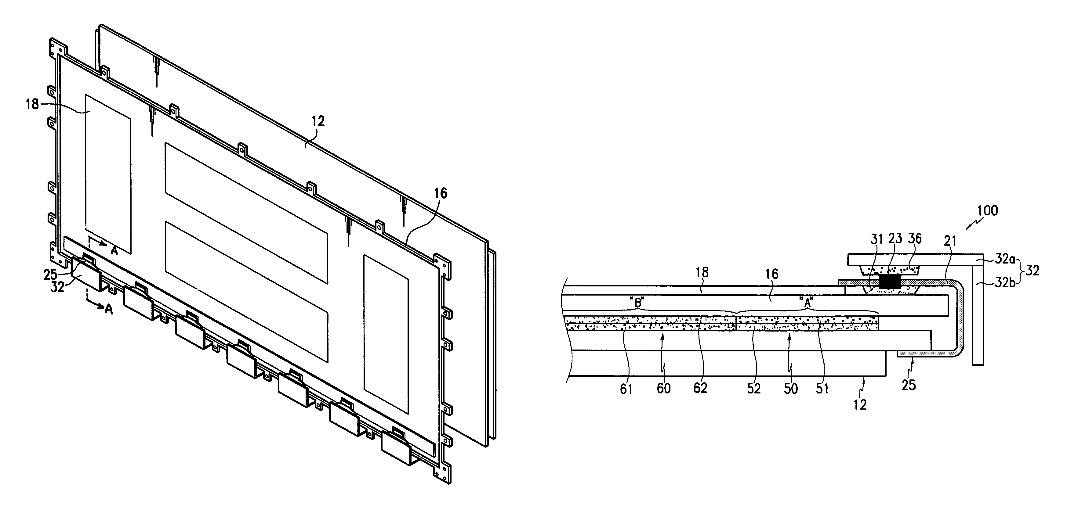
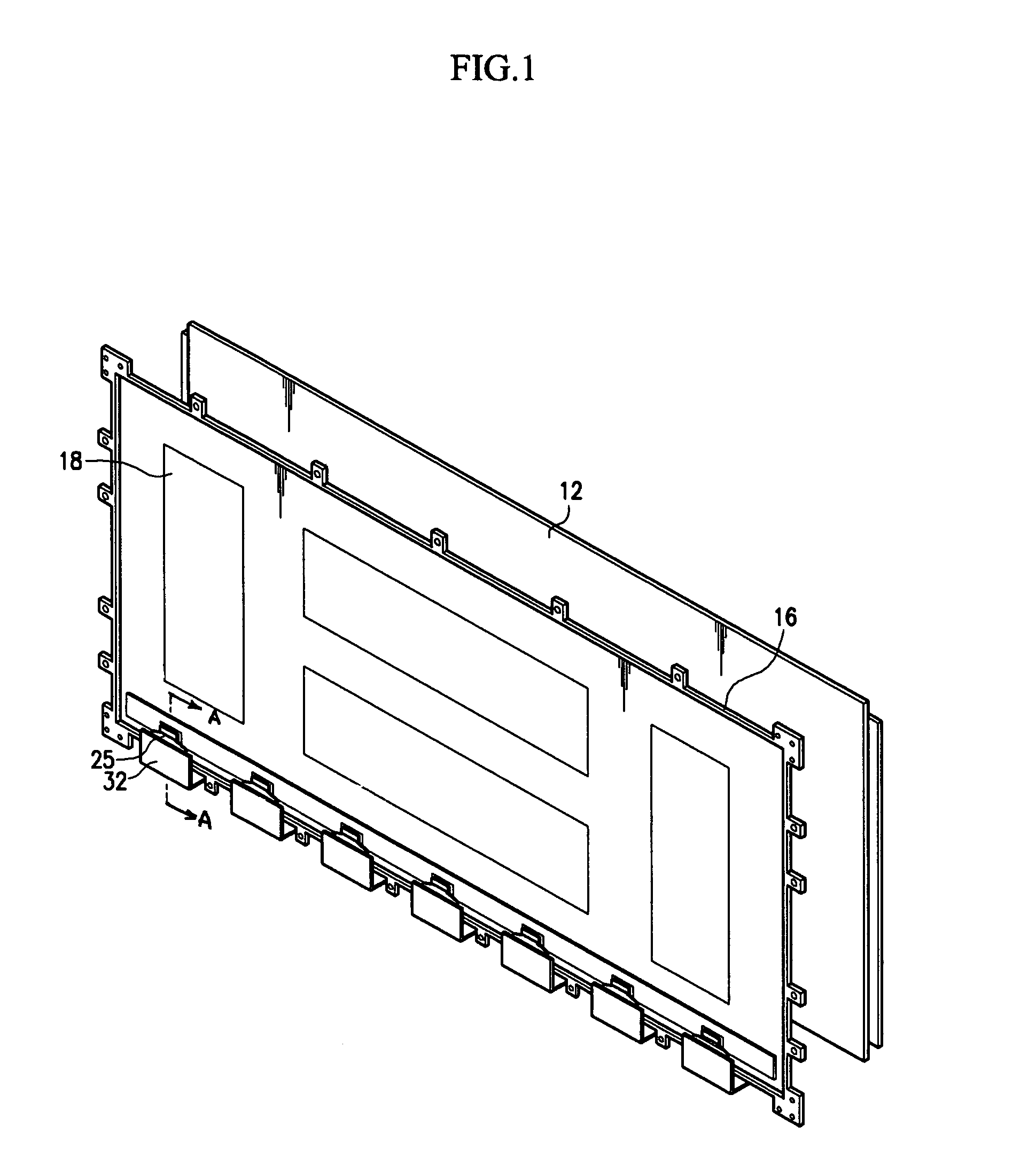
[0039]FIG. 1 is an exploded perspective view of a plasma display apparatus having a heat dissipating structure for a driver IC according to the present invention, and FIG. 2 is a cross-sectional view taken along the A-A line of FIG. 1.

[0040]With reference to FIG. 1 and FIG. 2, the plasma display apparatus includes a plasma display panel 12 (referred to hereinafter simply as a “PDP”), and a chassis base 16. The chassis base 16 is made of Cu, Fe, or the like, and the PDP 12 is mounted on one side surface thereof and a driving circuit 18 is mounted on the other side surface of the chassis base 16.

[0041]The PDP 12 of the plasma display device is mounted on a chassis base, with a front cover (not shown) on the outside of the PDP 12 and a rear cover (not shown) on the outside of a chassis base.

[0042]Electrodes extending from the periphery of the PDP 12 are electrically connected to the driving circuit 18 to receive the signals required for driving the PDP 12.

[0043]A driver IC 23 is dispos...

second embodiment

[0054]FIG. 3 is a cross-sectional view of a heat dissipating structure for a driver IC 23 according to the present invention.

[0055]With reference to FIG. 3, a plasma display apparatus according to the second embodiment of the present invention has a structure in which a third thermal conduction medium 43 in the form of a sheet is interposed between the driver IC 23 and the first thermal conduction medium 41.

[0056]In this embodiment, the third thermal conduction medium 43 is disposed between the driver IC 23 and a first portion 32a of a cover plate 32, and the first thermal conduction medium 41 is disposed between the first portion 32a of the cover plate 32 and the thermal conduction medium 41. The cover plate 32 can also have a second portion 32b extending from one distal end of the first portion 32a toward the peripheral edge of the PDP 12 and intersecting with the first portion 32a so as to support the second portion 32b.

[0057]The third thermal conduction medium 43 can be formed ...

third embodiment

[0061]FIG. 4 is an exploded perspective view of a plasma display apparatus according to the present invention, and FIG. 5 is a partial sectional perspective view of the chassis base shown in FIG. 4. FIG. 6 is a combinatorial sectional view of the plasma display apparatus shown in FIG. 4.

[0062]As shown in FIGS. 4 to 6, the plasma display apparatus 100 basically includes a PDP 12, and a chassis base 16. A front cover (not shown) externally surrounds the PDP 12, and a rear cover (not shown) externally surrounds the chassis base 16. The front and the rear covers are combined with each other to thereby complete a plasma display apparatus set.

[0063]The chassis base 16 is formed with aluminum, copper, or iron. The PDP 12 is mounted on a one-sided surface of the chassis base 16, and a driving circuit unit 18 is mounted on the opposite-sided surface of the chassis base 16 to drive the PDP 12.

[0064]The PDP 12 displays the desired images by exciting phosphors with the vacuum ultraviolet rays g...


PUM


Abstract

A heat dissipation apparatus for use with a plasma display device and a method of conducting the heat generated in the plasma display panel and the driving ICs of the plasma display device to various surfaces of the device for dissipation to air. A first heat sink is disposed between the plasma display panel and the chassis base. The first heat sink is positioned at a first region where the heat generated from the driver ICs is substantially concentrated. A second heat sink is positioned at a second region between the plasma display panel and the chassis base where the heat generated by the plasma display panel is substantially concentrated. A number of additional thermal conduction media are also used in the various embodiments of the invention.

Description

CROSS REFERENCES TO RELATED APPLICATION[0001]This application claims priority to and the benefit of Korean Patent Application No. 10-2004-0014564 filed on Mar. 4, 2004 and Korean Patent Application No. 10-2004-0029918 filed on Apr. 29, 2004 in the Korean Intellectual Property Office, the entire contents of both of which are incorporated herein by reference.BACKGROUND OF THE INVENTION[0002]1. Field of the Invention[0003]The present invention relates to a plasma display device, and, more particularly, to a plasma display device that includes a cover plate to efficiently dissipate the heat produced by a driver IC.[0004]2. Description of Related Art[0005]Generally, a plasma display apparatus is a device where images are displayed on a plasma display panel (simply referred to hereinafter as the “PDP”) using the plasma generated through the gas discharging.[0006]With the plasma display apparatus, heat is generated during the process of discharging the gas in the PDP to generate plasma. Wh...

Claims


Application Information

Patent Timeline
Patent Type & Authority Patents(United States)
IPC IPC(8): H05K7/20G09G3/28H01J7/24H04N5/74G09F9/00H01J11/10H01J17/49
CPCH01J11/10H01J2211/66
Inventor KIM, HYOUKBAE, SUNG-WONAHN, JOONG-HA
Owner SAMSUNG SDI CO LTD
Learn More