
RF coil assembly and method for practicing magnetization transfer on magnetic resonance imaging and spectroscopy systems

a technology of magnetic resonance imaging and spectroscopy, applied in the field of nuclear magnetic resonance imaging (mri) and spectroscopy (mrs) methods and systems, can solve the problems of poor isolation, difficult tuning of bird cage coils, and inability to achieve substantial change in larmor frequency required to examine alternative spin species

Active Publication Date: 2009-03-24
WISCONSIN ALUMNI RES FOUND
View PDF47 Cites 29 Cited by
  • Summary
  • Abstract
  • Description
  • Claims
  • Application Information

AI Technical Summary

Benefits of technology

Enables simultaneous acquisition of MR signals from multiple spin species at different Larmor frequencies, improving signal-to-noise ratio and efficiency in multinuclear MRI, allowing for quantitative imaging and dynamic monitoring of metabolism with reduced subject motion artifacts.

Problems solved by technology

As indicated above, the birdcage coil is difficult to tune at more than one Larmor frequency and the substantial change in Larmor frequency required to examine these alternative spin species is not practical.
An important limitation of prior multinuclear coils is that they consist of multi-modal resonant structures such as birdcage or TEM volume resonators.
In addition, poor isolation tends to degrade efficiency for each component of the coil in question.
During the time interval between scans, subject motion may occur, making the co-registration of the two scans difficult.
Another difficulty in acquiring 13C MR signals is that the signals are split due to J-coupling with 1H spins.
This J-coupling reduces sensitivity and spectral resolution.
Inadequate isolation between resonant modes prevents simultaneous operation of conventional multi-nuclear coil designs, which decreases the efficiency of spin exchange in the NOE experiment, particularly at high field strengths (e.g. 3 Tesla) where SAR limitations also occur.
This leads to spatially variable saturation and magnetization transfer that is undesirable for quantitative imaging applications.

Method used


Image

  • RF coil assembly and method for practicing magnetization transfer on magnetic resonance imaging and spectroscopy systems
  • RF coil assembly and method for practicing magnetization transfer on magnetic resonance imaging and spectroscopy systems
  • RF coil assembly and method for practicing magnetization transfer on magnetic resonance imaging and spectroscopy systems

Examples


Embodiment Construction

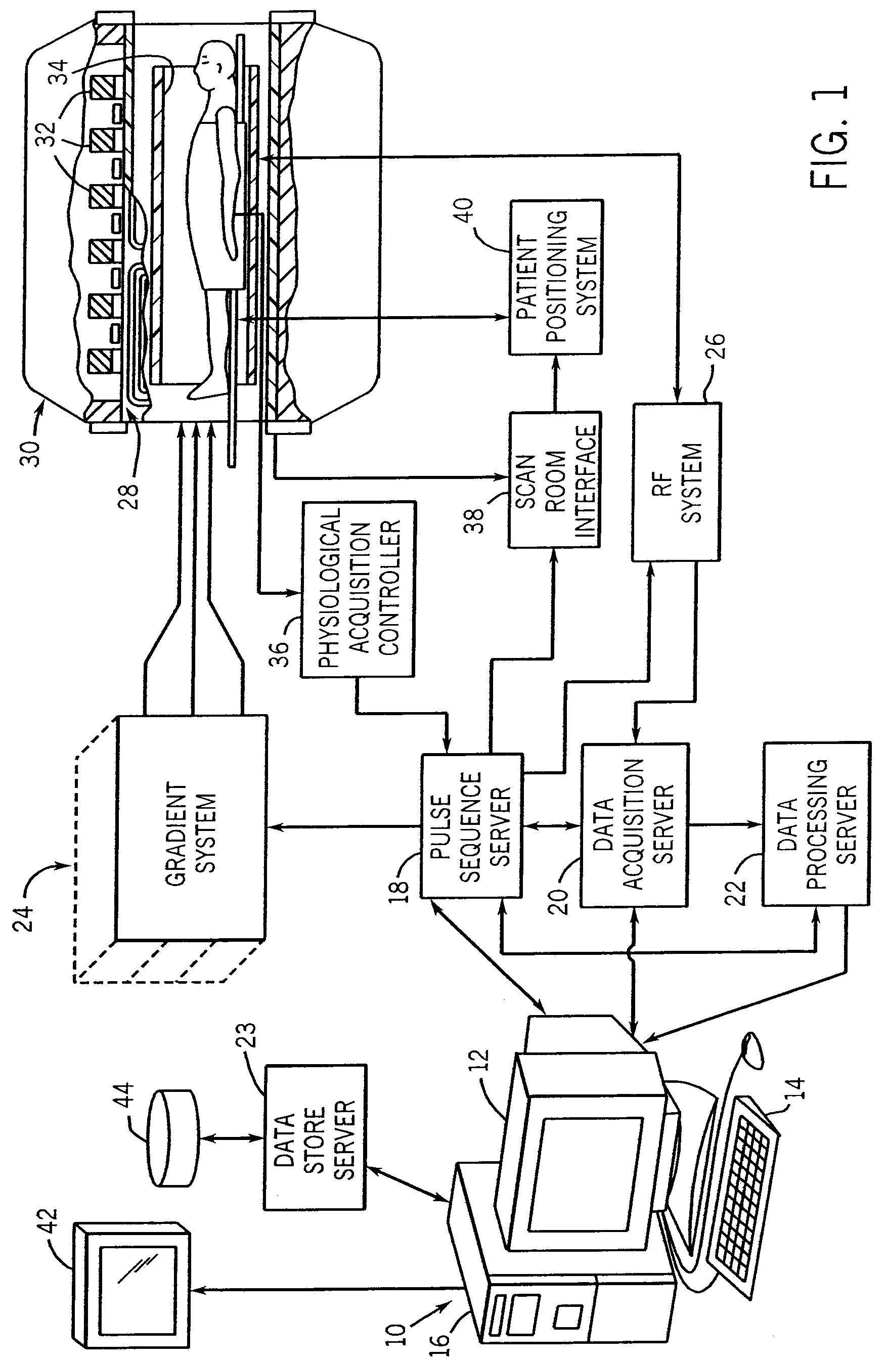
[0029]Referring particularly to FIG. 1, the preferred embodiment of the invention is employed in an MRI system. The MRI system includes a workstation 10 having a display 12 and a keyboard 14. The workstation 10 includes a processor 16 which is a commercially available programmable machine running a commercially available operating system. The workstation 10 provides the operator interface which enables scan prescriptions to be entered into the MRI system.

[0030]The workstation 10 is coupled to four servers: a pulse sequence server 18; a data acquisition server 20; a data processing server 22, and a data store server 23. In the preferred embodiment the data store server 23 is performed by the workstation processor 16 and associated disc drive interface circuitry. The remaining three servers 18, 20 and 22 are performed by separate processors mounted in a single enclosure and interconnected using a 64-bit backplane bus. The pulse sequence server 18 employs a commercially available micro...


PUM


Abstract

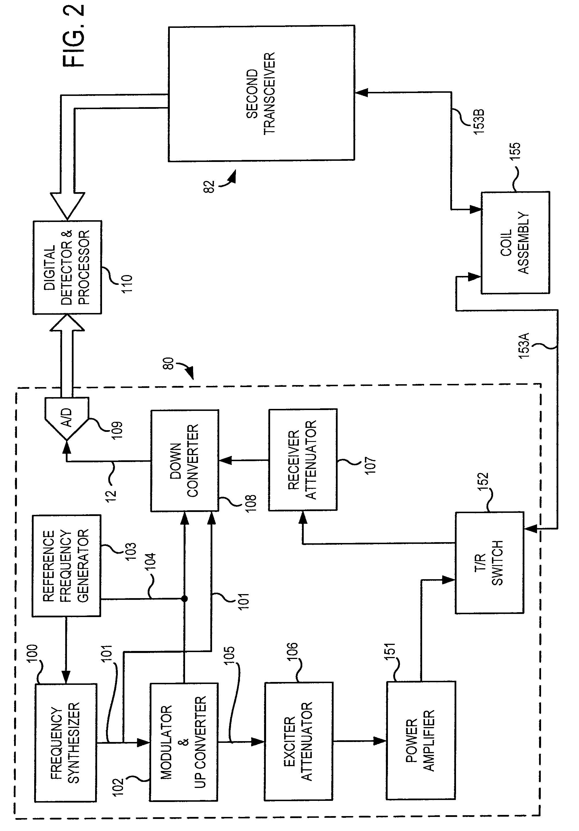
An RF coil assembly for an MRI system includes a resonator formed by a cylindrical shield and pairs of opposing conductive legs disposed symmetrically around a central axis and extending the axial length of the shield. One set of conductive leg pairs is tuned to operate at the Larmor frequency of 13C and another set is tuned to operate at the Larmor frequency of 1H. Drive circuitry operates the RF coil assembly to produce 1H spin magnetization which is transferred to 13C magnetization by the nuclear overhauser effect and to acquire MR data from the 13C spins. Multinuclear measurements can be made simultaneously at different Larmor frequencies.

Description

CROSS REFERENCE TO RELATED APPLICATIONS[0001]This application is a continuation-in-part of U.S. patent application Ser. No. 11 / 726,643, filed Mar. 22, 2007, and titled “RF Coil Assembly for Magnetic Resonance Imaging and Spectroscopy Systems”, which is hereby incorporated by reference.STATEMENT REGARDING FEDERALLY FUNDED RESEARCH[0002]This invention was made with United States government support awarded by the following agency: NIH grants: HL069116 and HL066488. The United States has certain rights in this invention.FIELD OF THE INVENTION[0003]The field of the invention is nuclear magnetic resonance imaging (MRI) and spectroscopy (MRS) methods and systems. More particularly, the invention relates to coils used to apply radio frequency (RF) magnetic fields in magnetization transfer scans and to receive NMR signals produced in response.BACKGROUND OF THE INVENTION[0004]When a substance such as human tissue is subjected to a uniform magnetic field (polarizing field B0) applied along the...

Claims


Application Information

Patent Timeline
Patent Type & Authority Patents(United States)
IPC IPC(8): G01V3/00
CPCG01R33/345G01R33/3453G01R33/3635G01R33/365G01R33/3678G01R33/3685G01R33/5659G01R33/5601G01R33/5605
Inventor FAIN, SEAN B.ERICKSON, MATTHEW G.KURPAD, KRISHNA N.HOLMES, JAMES H.GRIST, THOMAS M.
Owner WISCONSIN ALUMNI RES FOUND
Learn More