
Motor driving apparatus of washing and drying machine

a technology of motor driving and washing machine, which is applied in the direction of multiple ac dynamo-electric motor control, and drying solid materials with hea

Inactive Publication Date: 2009-03-17
PANASONIC CORP
View PDF6 Cites 53 Cited by
  • Summary
  • Abstract
  • Description
  • Claims
  • Application Information

AI Technical Summary

Benefits of technology

"The motor-driving apparatus of this washing and drying machine has a rectifying circuit that converts AC power into DC power, and multiple inverter circuits that convert DC power into AC power. The apparatus also includes a first motor for driving the rotation drum, a second motor for driving the compressor of a heat pump, a third motor for driving the blow fan that sends air to the heat exchanger of the heat pump, and a controller that controls the inverter circuits. The controller simultaneously drives all three motors using sinusoidal-wave control of each inverter circuit. The technical effect of this invention is to provide a more efficient and effective washing and drying machine that drives all necessary motors simultaneously, resulting in improved performance and efficiency."

Problems solved by technology

However, a conventional motor-driving apparatus of a washing and drying machine has following problems.
Adopting an inverter circuit that drives a motor with rectangular waves of 120° makes loud vibration noise.
Similarly, adopting an inverter circuit that drives a motor with sinusoidal waves, due to differences in revolution speed of each motor, carrier frequencies and processors (although a description on the in-detail configuration is not given), the sinusoidal-wave control is interfered by power switching noise.
As a result, the aforementioned configuration has difficulty in obtaining a stable driving in a practical use.

Method used


Image

  • Motor driving apparatus of washing and drying machine
  • Motor driving apparatus of washing and drying machine
  • Motor driving apparatus of washing and drying machine

Examples


first embodiment

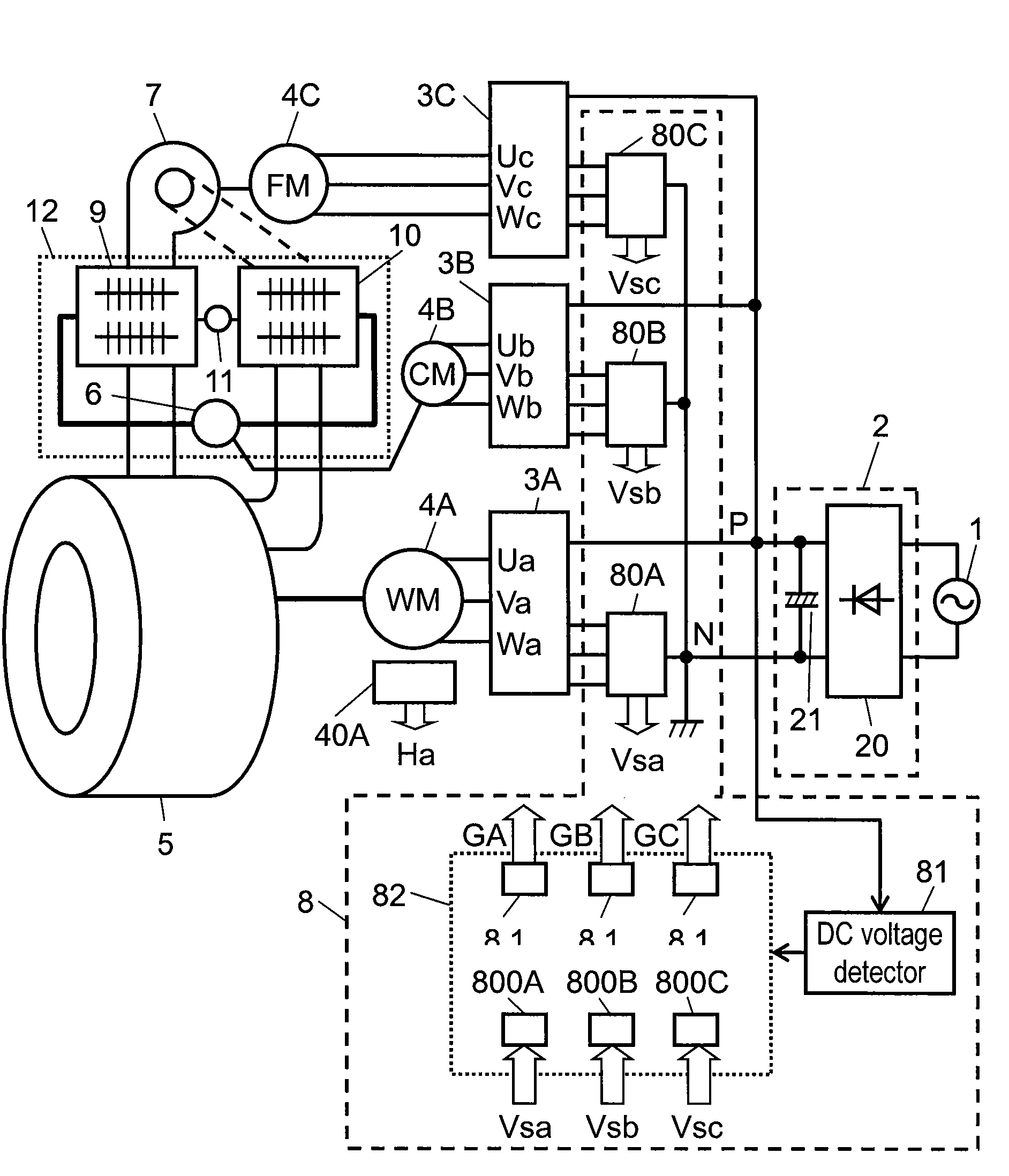
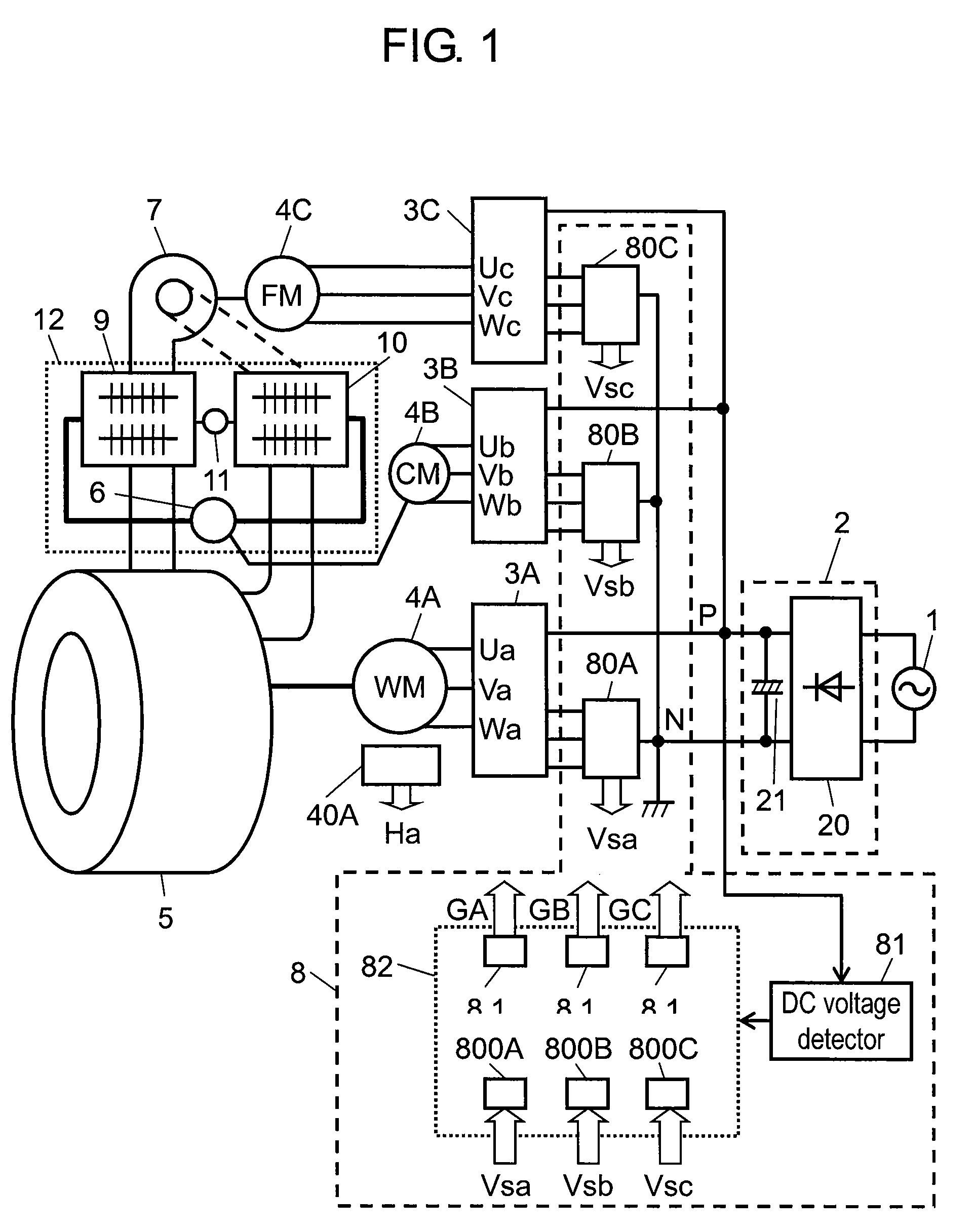
[0017]FIG. 1 is a block diagram of a motor-driving apparatus of a washing and drying machine in accordance with the first exemplary embodiment of the present invention.

[0018]In FIG. 1, alternating current (AC) power from AC power supply is fed to rectifying circuit 2 composed of full-wave rectifying circuit 20 and electrolytic capacitor 21 to convert into direct current (DC) power. The DC power is further converted into three-phase AC power, through first inverter circuit 3A, second inverter circuit 3B and third inverter circuit 3C, for driving rotation drum-driving motor (first motor) 4A, compressor-driving motor (second motor) 4B and blow fan-driving motor (third motor) 4C.

[0019]Although the description above shows a configuration where rectifying circuit 2 includes single electrolytic capacitor 21, in the case of single-phase 100-V input, practically used is a full-wave voltage-doubler rectifying connection where the circuit includes a plurality of electrolytic capacitors 21. In ...

second embodiment

[0119]FIG. 9 is a block diagram of an A / D converter in accordance with the second exemplary embodiment of the present invention. FIG. 10 shows operation waveforms of the A / D converter. Including other parts (not shown in here), the configuration constitutes a heat-pump type washing and drying machine, as is in the case of the first embodiment.

[0120]In FIG. 9, Receiving input selection signal Cs, multiplexer 800E selects phase current signals Iu, Iv and Iw of one motor according to signal Cs. For example, when first motor 4A is selected, A / D converter 850A converts the phase current signals Iu, Iv and Iw of motor 4A into digital output Dia.

[0121]Second motor 4B and third motor 4C have a configuration the same as above; the conversion is separately carried out by motor in A / D converters 850B and 850C.

[0122]In FIG. 10, triangular carrier-wave Ca with a frequency of 16 kHz has a peak at time t0. At this time, overflow pulse signal Ct is produced by an interrupt signal. All of motors 4A,...

third embodiment

[0132]FIG. 11 is a block diagram of a washing and drying machine of the third exemplary embodiment. The configuration of the embodiment is similar to that of the first embodiment (FIG. 1) with the exception that first current detector 80A and A / D converter 800A for detecting current signal Vsa of first motor 4A are removed.

[0133]According to the third embodiment, rotation drum-driving motor 4A does not adopt the vector control or the reactive current constant control. Instead, motor 4A operates on the sinusoidal-wave driving through the following way: obtaining the rotor position and actual speed from a position detecting signal fed from position detector 40A; determining the phase and amount of voltage Va applied to motor 4A by set speed, the amount of clothes, with reference to a table; and controlling PWM controller 810A so that voltage with a sinusoidal waveform is applied to motor 4A. Through the control above, the configuration offers current with a substantially sinusoidal wa...


PUM


Abstract

With the use of three inverter circuits controlled by a single processor, the controller of the motor-driving apparatus provides a rotation drum-driving motor, a compressor-driving motor and a blow fan-driving motor with a simultaneous sinusoidal-wave control. The configuration above offers stable sinusoidal-wave drive, reducing vibration noise of the rotation drum, the compressor and the blow fan.

Description

FIELD OF THE INVENTION[0001]The present invention relates to a motor-driving apparatus of a washing and drying machine that drives a plurality of motors at the same time with the use of a plurality of inverter circuits.BACKGROUND ART[0002]Conventionally, such a motor-driving apparatus of a washing and drying machine has a plurality of inverter circuits that drives a plurality of motors so that a rotation drum, a compressor and a blow fan are driven by each pair of an inverter circuit and a motor. For example, such a washing and drying machine is disclosed in Japanese Patent Unexamined Publication No. 2005-198933.[0003]However, a conventional motor-driving apparatus of a washing and drying machine has following problems. Adopting an inverter circuit that drives a motor with rectangular waves of 120° makes loud vibration noise. Similarly, adopting an inverter circuit that drives a motor with sinusoidal waves, due to differences in revolution speed of each motor, carrier frequencies an...

Claims


Application Information

Patent Timeline
Patent Type & Authority Patents(United States)
IPC IPC(8): H02P27/08D06F58/28H02P5/74D06F25/00
CPCD06F37/304D06F58/206H02P21/0035D06F2202/12Y02B40/52H02P21/22Y02B40/00D06F2103/48D06F34/08D06F2105/48D06F2103/46D06F58/26D06F58/10D06F2105/28D06F2105/30
Inventor ASADA, KAZUHIKOKIUCHI, MITSUYUKIHAGIWARA, HISACHISAITO, HIROYUKI
Owner PANASONIC CORP
Learn More