
Method of manufacturing image display, image display and adhesive optical film

a technology of adhesive optical film and image display, which is applied in the direction of polarising elements, solid-state devices, controlling lamination, etc., can solve the problems of scattered bright spots, large scratching of glass substrate surface, so as to avoid display defects, sufficient softness, and sufficient softness

Active Publication Date: 2009-03-17
NITTO DENKO CORP
View PDF9 Cites 14 Cited by
  • Summary
  • Abstract
  • Description
  • Claims
  • Application Information

AI Technical Summary

Benefits of technology

The present invention provides a method of manufacturing an image display by using an adhesive optical film to prevent display defects caused by scratches on the panel substrate surface of the image display panel. The adhesive optical film has a pressure-sensitive adhesive layer that can fill the scratch and prevent display defects. The method involves selecting an adhesive optical film that satisfies a formula based on the half-length of the scratch and the thickness of the pressure-sensitive adhesive layer. The use of this adhesive optical film can effectively avoid display defects and improve the quality of image displays.

Problems solved by technology

When an optical film is stuck via a pressure-sensitive adhesive layer to glass substrates, such a scratch can form a void, which can cause display defects such as scattered bright spots.
When the glass substrate is subjected to a chemical treatment or a polishing process for the production of thin liquid crystal display panels, the scratch can become larger.
On the other hand, after a liquid crystal display panel is assembled with a glass substrate, the surface of the glass substrate can also be scratched during transportation or some processes.
In such a case, it is difficult to reproduce the substrate in the above-mentioned manner.

Method used

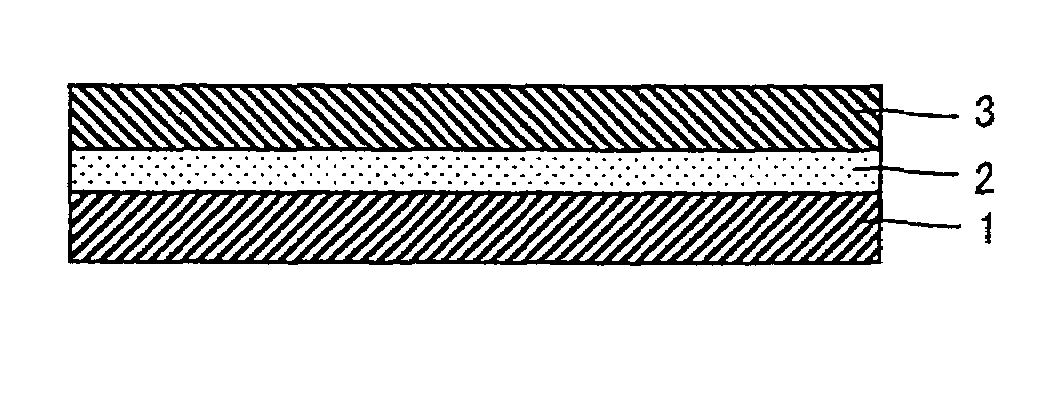

Image

  • Method of manufacturing image display, image display and adhesive optical film
  • Method of manufacturing image display, image display and adhesive optical film

Examples


example 1

(Preparation of Pressure-sensitive Adhesive)

[0094]In 100 pats of ethyl acetate, 100 parts of butyl acrylate, 0.2 parts of 2-hydroxyethyl acrylate, 2 parts of acrylic acid, and 2 parts of azobisisobutyronitrile were allowed to react under stirring at 60° C. for 10 hours to form a solution of an acrylic polymer with a weight average molecular weight of 1300000. Based on 100 parts of the polymer solid, 0.5 parts of an isocyanate type crosslinking agent (Coronate L manufactured by Nippon Polyurethane Co., Ltd.) was added to the polymer solution to prepare a pressure-sensitive adhesive solution.

(Preparation of Adhesive Optical Film)

[0095]An 80 μm-thick polyvinyl alcohol film was stretched to five times in an aqueous iodine solution and then dried. A triacetyl cellulose film was adhered with an adhesive to both sides of the stretched film to form a polarizing film.

[0096]The prepared pressure-sensitive adhesive solution was applied to a releasable film so as to form a 40 μm-thick pressure-...

example 2

(Preparation of Pressure-sensitive Adhesive)

[0097]A pressure-sensitive adhesive solution was prepared using the process of Example 1 except that the amount of the crosslinking agent was changed to 0.3 parts.

(Preparation of Adhesive Optical Film)

[0098]An adhesive polarizing film was prepared using the process of Example 1 except that the above prepared pressure-sensitive adhesive solution was used to form a 25 μm-thick pressure-sensitive adhesive layer.

example 3

(Preparation of Pressure-sensitive Adhesive)

[0099]In 100 parts of ethyl acetate, 80 parts of 2-ethylhexyl acrylate, 19 parts of butyl acrylate, 1 part of 4-hydroxybutyl acrylate, and 2 parts of azobisisobutyronitrile were allowed to react under stirring at 60° C. for 10 hours to form a solution of an acrylic polymer with a weight average molecular weight of 1200000. Based on 100 parts of the polymer solid, 0.05 parts of an isocyanate type crosslinking agent (Coronate L manufactured by Nippon Polyurethane Co., Ltd.) was added to the polymer solution to form a pressure-sensitive adhesive solution.

(Preparation of Adhesive Optical Film)

[0100]An adhesive polarizing film was prepared using the process of Example 1 except that the above prepared pressure-sensitive adhesive solution was used to form a 15 μm-thick pressure-sensitive adhesive layer.


PUM

PropertyMeasurementUnit
creep displacementaaaaaaaaaa

Abstract

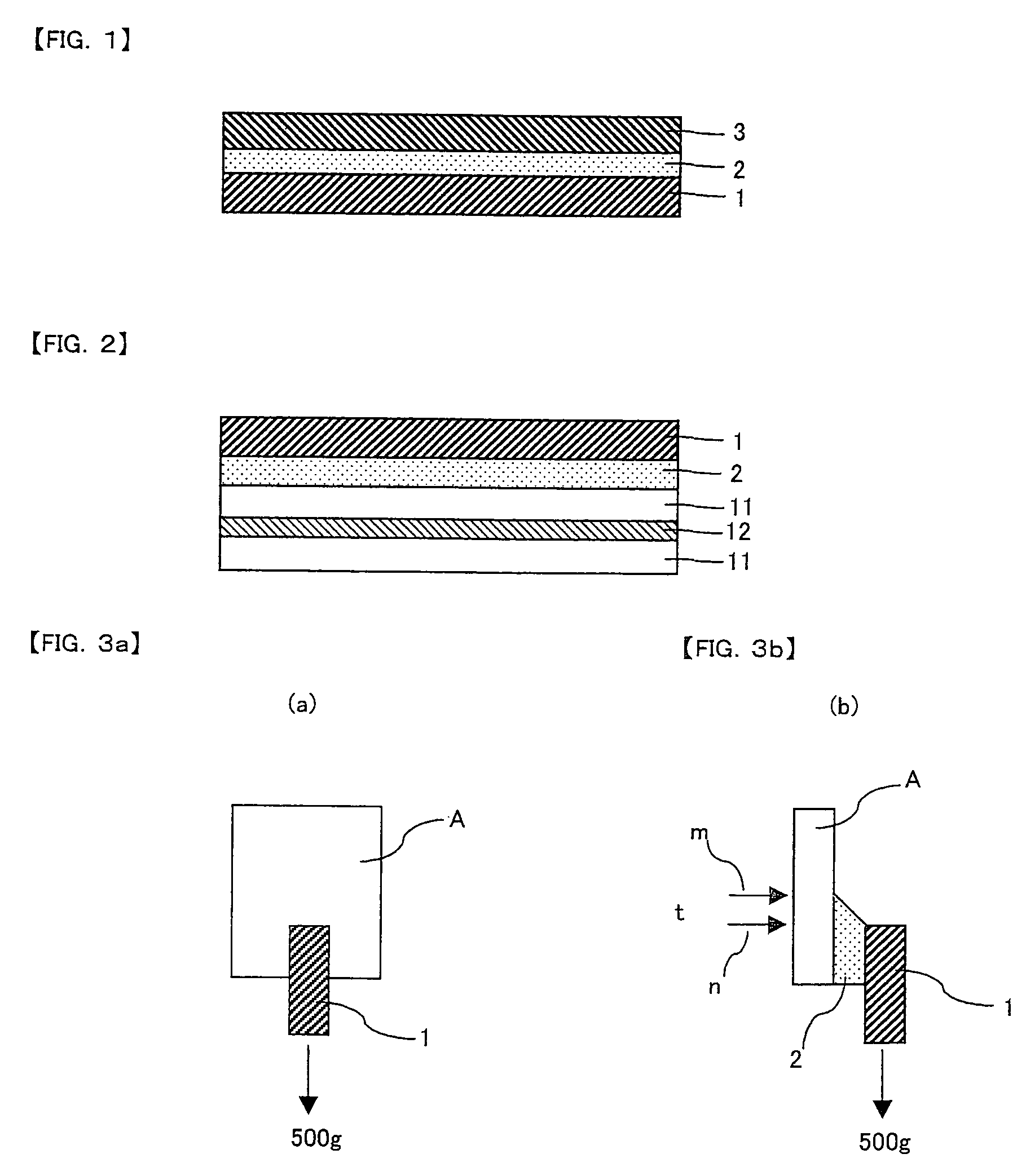
The invention is directed to a method of manufacturing an image display, comprising the step of sticking an adhesive optical film to an image display panel substrate surface having a display defect-inducible scratch, wherein the adhesive optical film is selected and used according to the image display panel such that the formula: Y×(0.97X+0.45)>0.19Z−0.006 is satisfied, wherein X (mm) is the amount of creep displacement one hour after a load of 500 g is applied at 23° C. to a 10 mm square of an adhesion area of the adhesive optical film stuck to the panel substrate, Y (mm) is the thickness of a pressure-sensitive adhesive layer of the adhesive optical film, and Z (mm) is a half length of the length of long side of the scratch of the image display panel substrate surface. According to the invention, a display defect, which would otherwise be caused by an scratch of the image display panel substrate, is avoided by filling the scratch with the pressure-sensitive adhesive layer of the adhesive optical film.

Description

[0001]This application is the U.S. National Phase under 35 U.S.C. §371 of International Application PCT / JP2003 / 016449, filed Dec. 22, 2003, which claims priority to Japanese Patent Application No. 2003-825, filed Jan. 7, 2003. The International Application was not published under PCT Article 21(2) in English.TECHNICAL FIELD[0002]The invention relates to a method of manufacturing an image display, which is applicable with an image display panel having a scratch that can cause a display defect, and to an image display manufactured by the concerned method. The image display may be a liquid crystal display, an organic EL display, a PDP, or the like. The invention also relates to an adhesive optical film comprising an optical film and a pressure-sensitive adhesive layer which is provided on one side of the optical film so as to stick to a panel substrate of an image display panel. The optical film may be a polarizing film, a retardation film, a compensation film, a brightness enhancement...

Claims


Application Information

Patent Timeline
Patent Type & Authority Patents(United States)
IPC IPC(8): B32B41/00G02B5/30G02F1/1333G02F1/1335G09F9/00H01L51/50H05B33/02
CPCG02F1/1333Y10T428/28Y10T156/1089Y10T156/1092G02F1/1335
Inventor HAYASHI, OSAMUSATAKE, MASAYUKIOGASAWARA, AKIKO
Owner NITTO DENKO CORP
Learn More