
Resource virtualization switch

a virtualization switch and resource technology, applied in the field of resource virtualization, can solve the problems of high cost of providing redundant resources in each server in a server rack or server farm, low utilization rate, and waste of resources

Active Publication Date: 2009-03-10
ORACLE INT CORP
View PDF14 Cites 328 Cited by
  • Summary
  • Abstract
  • Description
  • Claims
  • Application Information

AI Technical Summary

Benefits of technology

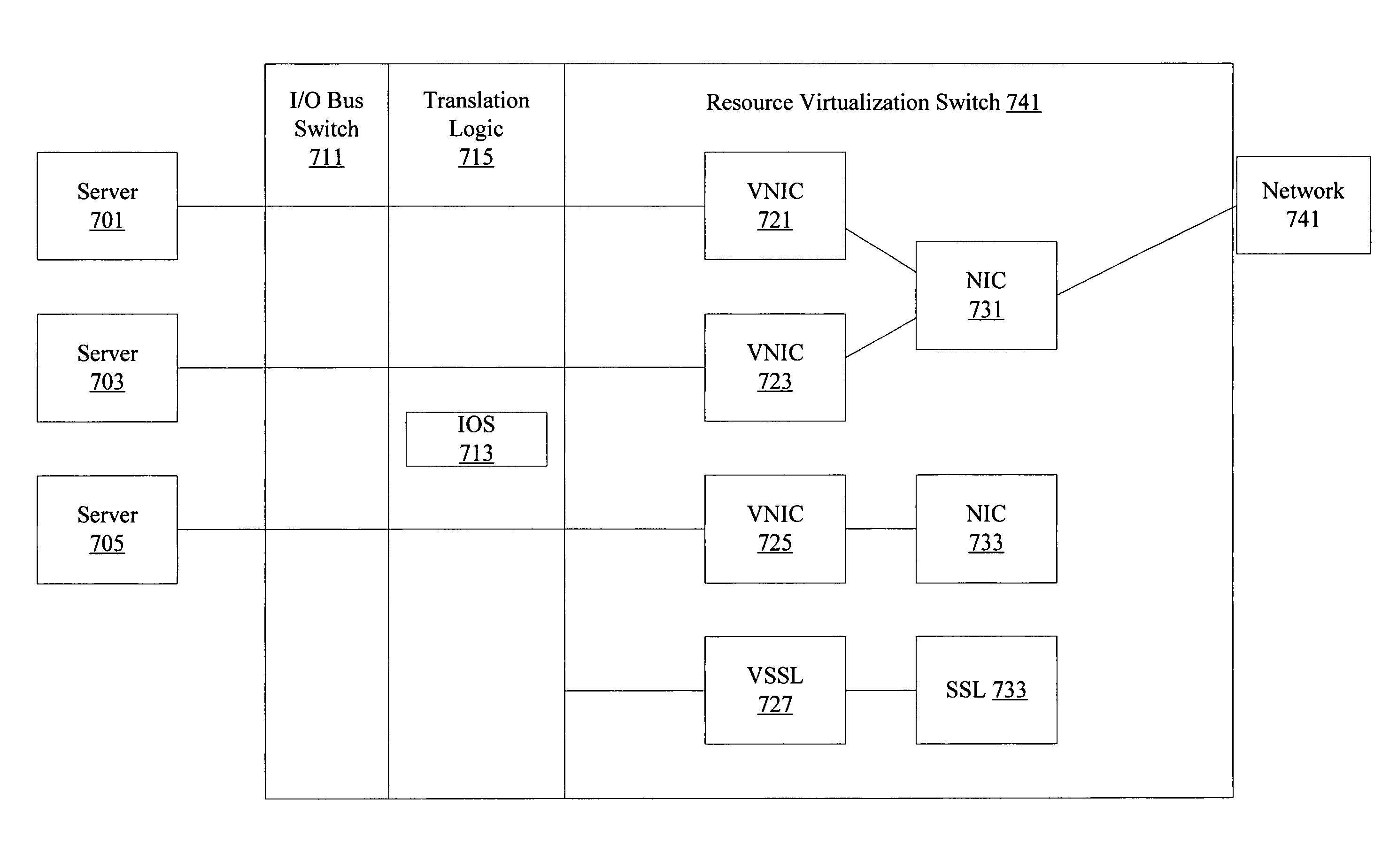
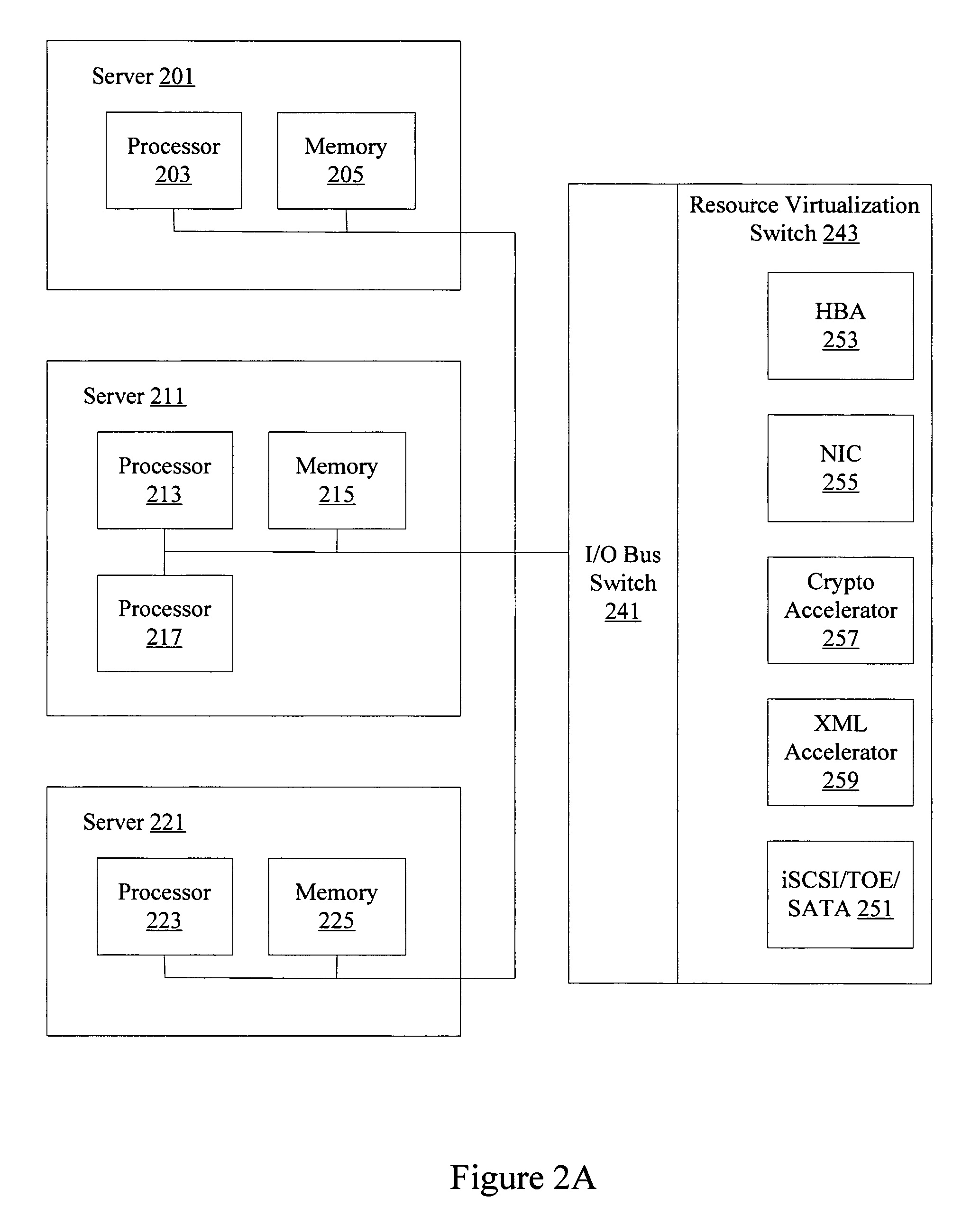
The patent describes a system that allows for the efficient allocation and sharing of resources among multiple servers. This is achieved through a resource virtualization switch that connects multiple servers over an I / O bus fabric. The switch includes virtualization logic that obtains data from the servers and provides it to a selected resource. The system also includes a bus interface, peripherals, and a processor for managing requests for access to peripherals. The technical effects of this invention include improved performance, reliability, and flexibility in resource allocation and sharing.

Problems solved by technology

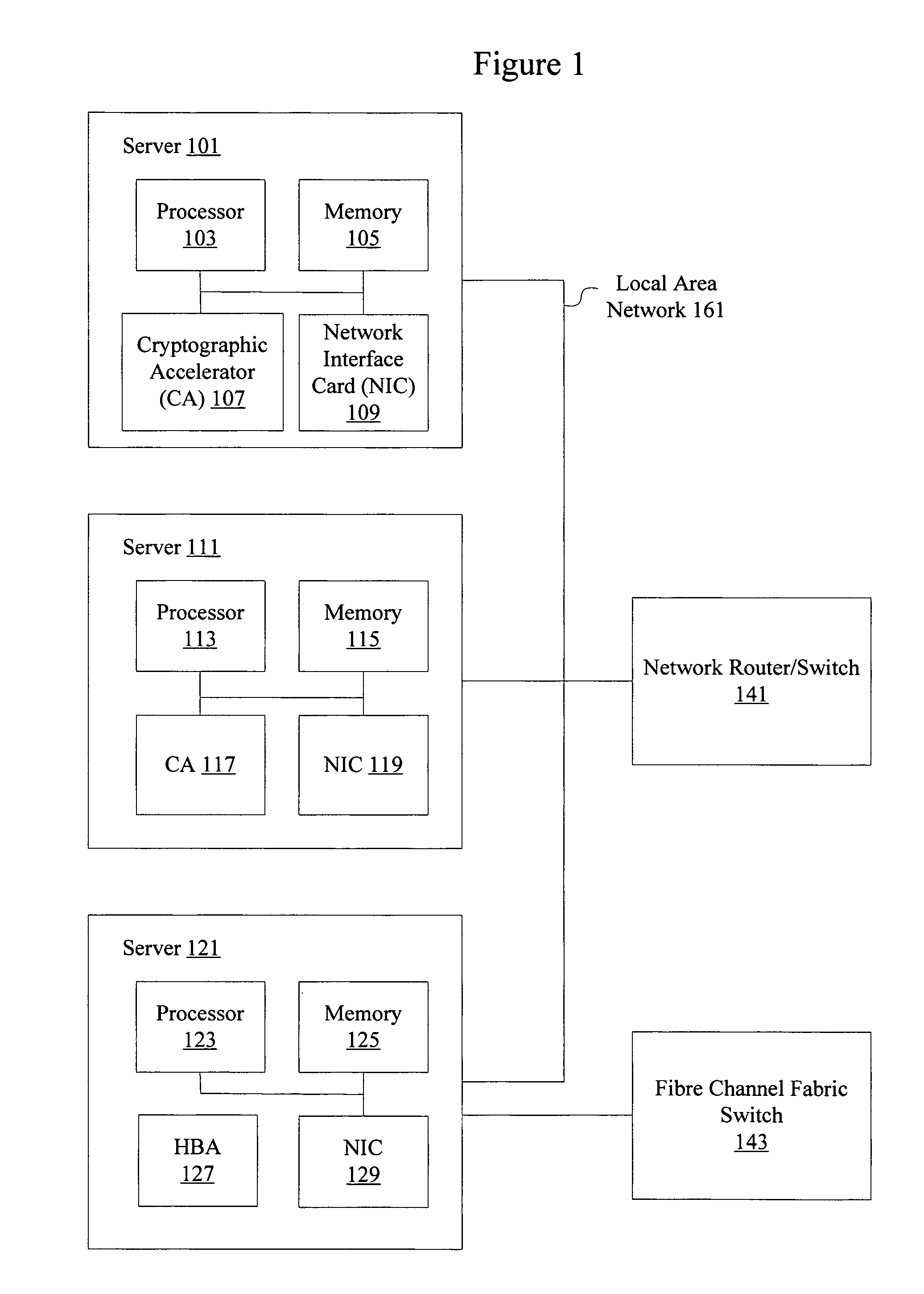
However, providing redundant resources in each server in a server rack or server farm can be expensive.
Redundancy can typically only be provided in a rigid and inflexible manner.
A large number of links and redundant Ethernet links are needed to connect servers to networks.
Resources are over-provisioned resulting in overall waste and low utilization.
Resource assignment on a per server or a per processor basis also limits the ability to reconstruct or reconfigure a resource environment.
For example, XML accelerators may have to be included on each server even though each accelerator may be underutilized.
Having a number of disparate servers also increases the complexity associated with individual system management.
Conventional system architectures create resource usage inefficiency, server management inefficiency, security loop holes, reconfiguration inflexibility, along with a number of other drawbacks.

Method used


Image

  • Resource virtualization switch
  • Resource virtualization switch
  • Resource virtualization switch

Examples


Embodiment Construction

[0031]Reference will now be made in detail to some specific examples of the invention including the best modes contemplated by the inventors for carrying out the invention. Examples of these specific embodiments are illustrated in the accompanying drawings. While the invention is described in conjunction with these specific embodiments, it will be understood that it is not intended to limit the invention to the described embodiments. On the contrary, it is intended to cover alternatives, modifications, and equivalents as may be included within the spirit and scope of the invention as defined by the appended claims.

[0032]For example, the techniques of the present invention will be described in the context of Peripheral Control Interface (PCI) Express, I / O buses, and Ethernet / Internet Protocol (IP) networks. However, it should be noted that the techniques of the present invention can be applied to a variety of different standards and variations to PCI Express, PCI-AS, buses, and IP ne...


PUM


Abstract

Methods and apparatus are provided for virtualizing resources including peripheral components and peripheral interfaces. Peripheral component such as hardware accelerators and peripheral interfaces such as port adapters are offloaded from individual servers onto a resource virtualization switch. Multiple servers are connected to the resource virtualization switch over an I / O bus fabric such as PCI Express or PCI-AS. The resource virtualization switch allows efficient access, sharing, management, and allocation of resources.

Description

CROSS-REFERENCE TO RELATED APPLICATIONS[0001]This application claims priority from U.S. Provisional Patent Application No. 60 / 590,450 titled METHODS AND APPARATUS FOR RESOURCE VIRTUALIZATION, filed on Jul. 22, 2004 by Shreyas Shah, Subramaniam Vinod, R. K. Anand, and Ashok Krishnamurthi, the entirety of which is incorporated by reference for all purposes.BACKGROUND OF THE INVENTION[0002]1. Field of the Invention[0003]The present invention relates to resource virtualization. In one example, the present invention relates to methods and apparatus for efficiently providing resources such as peripheral interfaces and peripheral components in a virtualized, shared, and redundant manner to multiple servers connected over an I / O bus interface.[0004]2. Description of Related Art[0005]A server or computing system generally includes one or more processors, memory, and peripheral components and peripheral interfaces. Examples of peripheral components include cryptographic accelerators, graphics...

Claims


Application Information

Patent Timeline
Patent Type & Authority Patents(United States)
IPC IPC(8): G06F13/00
CPCH04L67/1097G06F13/4022H04L49/70G06F13/12G06F13/128G06F13/42G06F13/4221G06F3/0601G06F3/0635G06F3/0662G06F3/0664G06F3/067G06F11/2005H04L12/4641H04L41/04H04L49/00H04L49/357
Inventor SHAH, SHREYASVINOD, SUBRAMANIAMANAND, RAMALINGAM K.KRISHNAMURTHI, ASHOK
Owner ORACLE INT CORP
Learn More