
Method for making a multilayer composite pressure vessel

a pressure vessel and composite technology, applied in the field of containers, can solve the problems of limited applicability, high manufacturing cost, and metal pressure vessel construction, and achieve the effect of improving adhesion and adhesion

Active Publication Date: 2009-03-03
ARDE
View PDF20 Cites 7 Cited by
  • Summary
  • Abstract
  • Description
  • Claims
  • Application Information

AI Technical Summary

Benefits of technology

[0012]As such it is the object of this invention to provide a high pressure light-weight pressure vessel that overcomes the drawbacks associated with the prior art and is constructed having improved adhesion between the inner liner and outer jacket layers. Additionally, it is an object of the present invention to provide a method of consistently manufacturing such pressure vessels with improved adhesion between the inner liner and outer jacket layers.

Problems solved by technology

Experience with such and similar all-metallic pressure vessel constructions has shown, on the other hand, that they are limited in applicability because they are either too heavy (a criterion that is of paramount importance for applications where weight is at a premium, such as in outer space applications), or expensive to manufacture, or prone to failure, especially due to metallic material fatigue at weakened or stress concentration regions after having been subjected to a number of pressurization and depressurization cycles.
However, the prior art methods of applying the wrapped jacket to the metal liner of the vessel suffers from many drawbacks.
This frequently results in roping / bridging of the fiber with a resulting loss of bearing pressure.
The variability in bearing pressure is a limiting factor in developing optimal adhesion of the overwrap layer to the metal liner.
Poor adhesion between the overwrap layer and the metal liner caused by irregular bearing pressure during the overwrap application can result in liner elastic stability / buckling failure.
The thin metal liner, as a standalone structural entity, is incapable of supporting the high bearing pressure imposed at zero or low pressure by the overlying composite after vessel autofrettage.
The elastic stability or buckling failure of the liner results in dramatic reductions in fatigue life, resulting through cracks in the metal liner and leakage of contents within a small number of cycles.

Method used


Image

  • Method for making a multilayer composite pressure vessel
  • Method for making a multilayer composite pressure vessel
  • Method for making a multilayer composite pressure vessel

Examples


Embodiment Construction

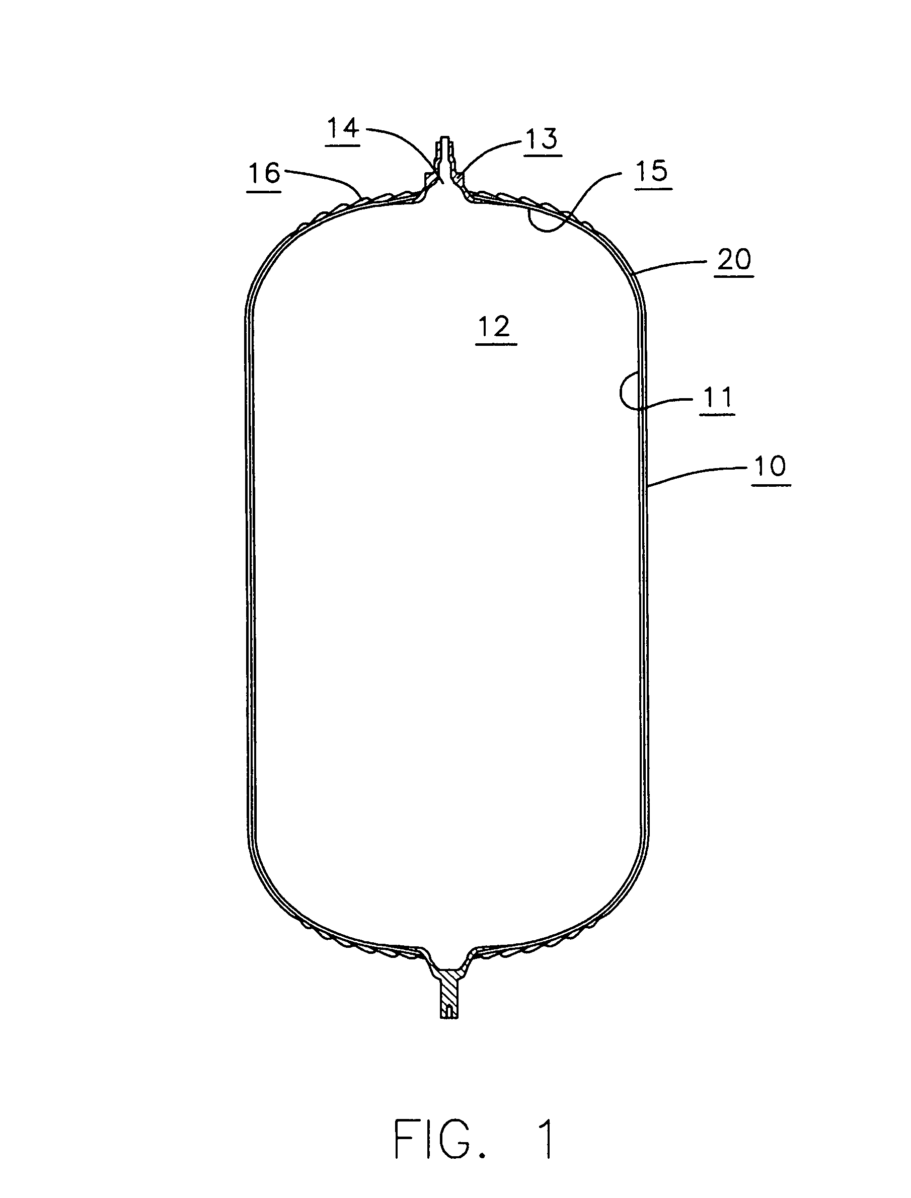
[0020]Referring now to the drawings, and initially to FIG. 1, it may be seen that the general reference numeral 10 identifies a pressure vessel embodying the present invention. Pressure vessel 10 (also referred to as vessel 10) has a main portion 11 that bounds an internal chamber or interior 12 of vessel 10, and a stem or neck portion 13 that projects out of the main portion 11 along an axis and is hollow to define a passage 14 for establishing communication between the interior 12 of the vessel 10 and its exterior.

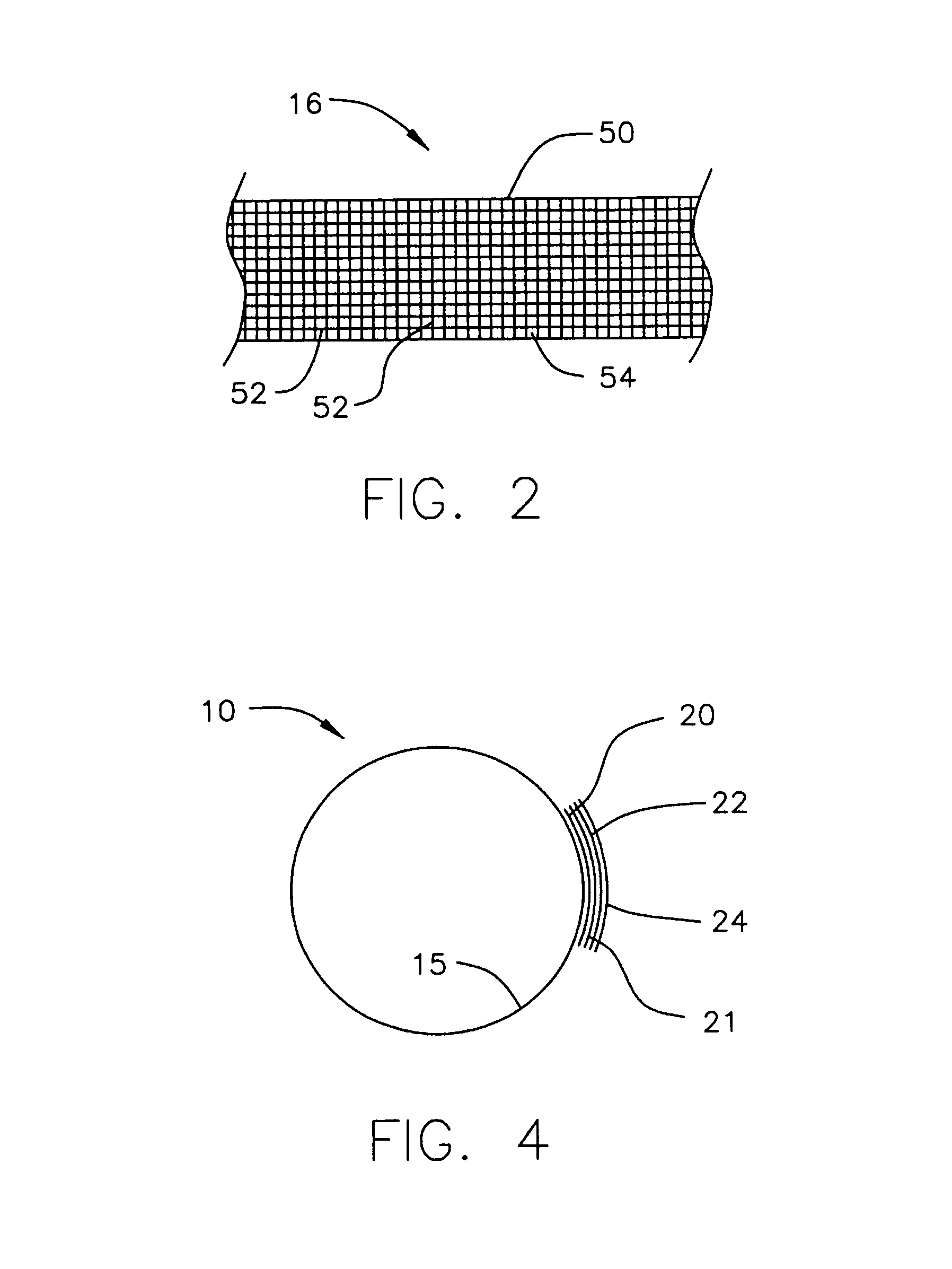
[0021]As illustrated in FIG. 1, the vessel 10 is of a multilayer or composite structure in that it includes an inner liner 15 and an outer jacket or overwrap 16 that surrounds the liner 15 and, more particularly, at least a main portion 11 of the liner that bounds interior 12. Liner 15 used in the vessel 10 of the present invention is preferably very thin, such that its thickness is chosen to be just above the minimum needed to prevent permeation of the medium contained ...


PUM

PropertyMeasurementUnit
temperatureaaaaaaaaaa
adhesiveaaaaaaaaaa

Abstract

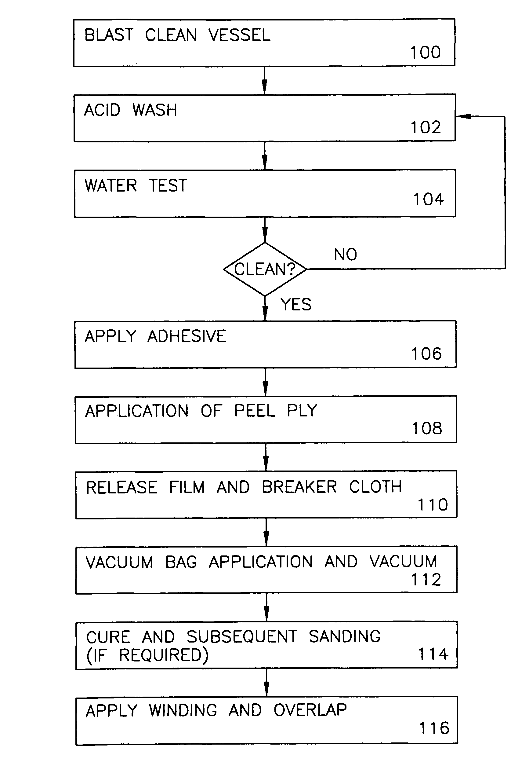
A method for manufacturing a pressure vessel includes the steps of obtaining a metal liner and applying a first layer of adhesive to an outer surface of the metal liner. The metal liner is then placed into a vacuum bag and a vacuum is applied, thus securing the adhesive to the outer surface of the metal liner. After curing of the adhesive, a filamentary material is wound around the liner, where the filamentary material adheres to the first layer of adhesive forming an overwrap layer on the outer surface of the metal liner, forming the pressure vessel.

Description

FIELD OF THE INVENTION[0001]The present invention relates to containers in general. More particularly, the present invention relates to light weight vessels capable of accommodating various media at relatively high pressures.BACKGROUND OF THE INVENTION[0002]In many technical fields, a need exists for storing various liquid or gaseous media, such as compressed or liquefied gases, for extended periods of time and frequently at very high pressures. Many attempts have already been made in the past to satisfy this need by developing lightweight pressurized medium containers or pressure vessels that would accommodate the pressurized medium without suffering leakage losses or structural damage.[0003]For a variety of reasons, not the least important of which is the relatively high ratio of pressure that the vessel walls are able to withstand to the weight of a vessel of a given capacity, it has been found advantageous to give such walls a multilayer or composite structure, including an inne...

Claims


Application Information

Patent Timeline
Patent Type & Authority Patents(United States)
IPC IPC(8): B65H81/00
CPCB29C70/86F17C1/16B32B37/12B32B38/0012B32B38/0036F17C1/06Y10T428/13F17C2201/0109F17C2201/056F17C2203/0604F17C2203/0619F17C2203/0636F17C2203/0663F17C2203/0673F17C2209/221F17C2209/227F17C2209/232F17C2223/0123F17C2223/0153F17C2223/035F17C2260/012F17C2260/036F17C2260/042F17C2270/0194Y10T428/1352Y10T428/1355
Inventor SNEDDON, KIRK
Owner ARDE
Learn More